
Signal Generator Circuit

The circuit designed for troubleshooting audio, video, and lower frequency RF amplifiers is crucial for diagnosing issues in these systems. It generates a signal characterized by a rich harmonic content, which is essential for testing the frequency response and linearity of amplifiers. The harmonic-rich signal can effectively reveal distortion, frequency response anomalies, and other performance-related issues within the amplifier circuits.
The circuit typically consists of a signal generator that produces a fundamental frequency, followed by a series of nonlinear components that introduce harmonics. These nonlinear components can include diodes, transistors, or specialized harmonic generation ICs. The output of the circuit may be connected to an oscilloscope or a spectrum analyzer to visualize the harmonic content and assess the amplifier's performance.
In audio applications, the generated signal can simulate complex waveforms, allowing for thorough testing of audio amplifiers. For video systems, the harmonic content can help in identifying issues related to bandwidth and signal integrity. In lower frequency RF applications, the circuit can assist in evaluating the linearity and gain of RF amplifiers, ensuring they operate within specified parameters.
In summary, this circuit serves as a vital tool for engineers and technicians in the field of electronics, providing a means to troubleshoot and optimize amplifier performance across various applications. Its ability to generate a harmonic-rich signal makes it an invaluable asset in the testing and maintenance of audio, video, and RF amplification systems. Useful for troubleshooting audio, video, and lower frequency RF amplifiers, this circuit generates a signal that is rich in harmonics.
Related Circuits
Replacing the LC modulation circuit with an active filter allows for the elimination of large and costly inductance coils in frequency shift key control demodulators. This approach not only reduces the size of the circuit but also enhances the...
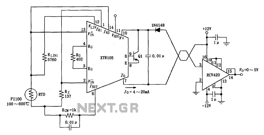
The circuit utilizes a Pt100 type resistance temperature detector (RTD). It operates within a temperature range of 100 to 600 °C, where the XTR105 outputs a current of 4 to 20 mA, and the RCV420 provides an output voltage...
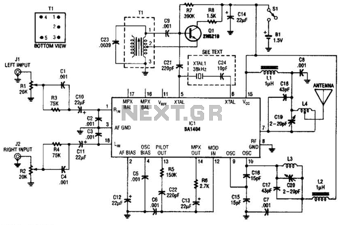
In this application, a BA1404 is utilized to generate an FM MPX baseband signal. This signal modulates a crystal oscillator (Q3) through a dual varactor series modulator. This transmitter can be used to play CD audio on an existing...
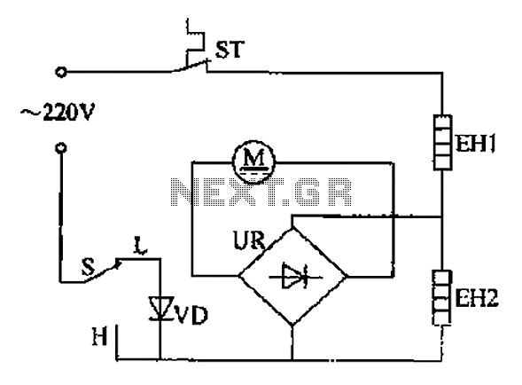
The comb electric circuit illustrated in Figure 1-3 features two temperature settings. By toggling switch S to either the L or H position, different temperatures can be achieved. Once switch S is activated, the circuit powers the heating wires...
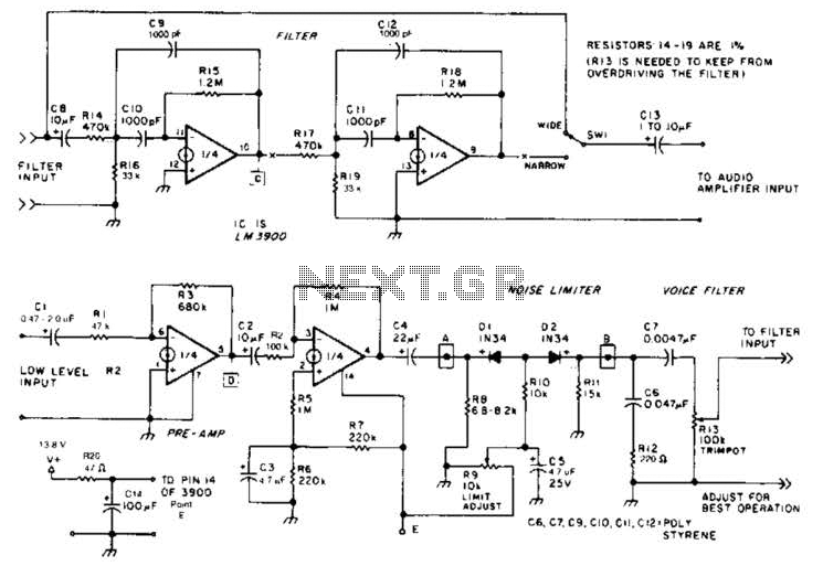
The noise limiter circuit features a preamplifier clipper and a switchable audio bandpass filter. Audio levels ranging from 5 to 50 mV are amplified in a preamplifier to several volts peak-to-peak, which are then sent to a clipper and...
Christmas is approaching, and it is the time of year when electronics students and hobbyists consider creating a Christmas circuit for their homes, particularly one that features flashing lights. Numerous circuits and kits are available that can flash various...