
Descrete Multistage Light Sequencer

The multistage light sequencer circuit is designed with simplicity and effectiveness in mind, utilizing discrete components to create a visually appealing light sequence. Each stage of the sequencer consists of a transistor, which acts as a switch for the corresponding light. The use of capacitors between stages is crucial, as they store charge and contribute to the timing of the light sequence. The charging and discharging behavior of these capacitors is key to the operation of the circuit.
In the initial state, when the circuit is powered, all capacitors are charged, and no lights are illuminated. The manual initiation process allows for the first stage to be activated, setting off the cascading effect of lights turning on and off. The design can be modified to include additional stages by adding more transistors and capacitors, which would allow for a longer sequence of lights.
The choice of component values, particularly the capacitors and resistors, plays a significant role in determining the timing of the sequencer. By adjusting these values, the rate at which the lights turn on and off can be fine-tuned to achieve the desired effect. The current gain of the transistors also impacts the performance of the circuit, as it determines how effectively each transistor can switch the load current for the lights.
This circuit can be employed in various applications, including decorative lighting, signaling, or as a teaching tool for understanding basic electronic principles. The absence of integrated circuits makes it an excellent project for those interested in learning about discrete component circuitry and the fundamentals of transistor operation.The drawing below illustrates a multistage light sequencer using descrete parts and no integrated circuits. The idea is not new and I hear a similar circuit was developed about 40 years ago using germanium transistors.
The idea is to connect the lights so that as one turns off it causes the next to turn on, and so forth. This is accomplished with a large capacitor between each stage that charges when a stage turns off and supplies base current to the next transistor, thus turning it on. Any number of stages can be used and the drawing below illustrates 3 small Christmas lights running at about 5 volts and 200mA.
The circuit may need to be manually started when power is applied. To start it, connect a momentary short across any one of the capacitors and then remove the short. You could use a manual push button to do this. Assume the circuit doesnt start when power is applied amd all lights are off and all three capacitors are charged to about 5 volts. We connect a jumper across the 220uF capacitor on the left which discharges the capacitor and turns on the 2nd stage transistor and corresponding light.
When the jumper is removed, the capacitor will start charging through the base of the stage 2 transistor and stage 1 light. This causes the stage 2 transistor to remain on while the capacitor continues to charge. At the same time, the capacitor connecting stage 2 and 3 will discharge through the 100 ohm resistor and diode and stage 2 transistor.
When the capacitor charging current falls below what is needed to keep stage 2 turned on, the transistor and light will turn off causing the voltage at the collector of the stage 2 transistor to rise to 5 volts. Since the capacitor connecting stage 2 and 3 has discharged and the voltage rises at the collector of stage 2, the capacitor from stage 2 and 3 will charge causing the 3rd stage to turn on and the cycle repeats for sucessive stages 4, 5, 6, 7.
and back to 1. The sequence rate is determined by the capacitor and resistor values (220uF and 100 ohms in this case), load current (200mA in this case), and current gain of the particular transistor used. This arrangement runs at about 120 complete cycles per minute for 3 lights, or about 167mS per light.
Faster or slower rates can be obtained with different capacitor values. 🔗 External reference
Related Circuits
The Traffic Light Hack is a simple interface designed to control lights within a traffic light enclosure. This device, acquired from a flea market, serves as an ambient information display. When connected to a computer, it can run programs...
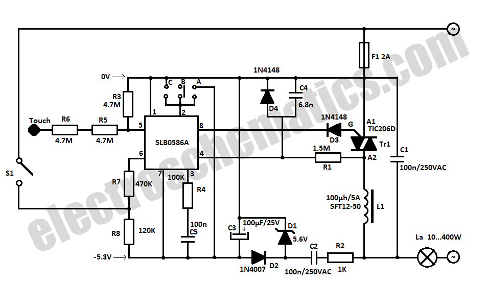
The SLB0586A integrated circuit from Siemens can be utilized to create a simple touch light dimmer circuit, allowing for the adjustment of lamp intensity. When paired with a TIC206D triac, this setup enables smooth regulation of light intensity for...
The circuit below illustrates the use of the LM741 integrated circuit (IC) in a light and dark sensor configuration. This circuit offers several features, including a 1 Watt LED spotlight, making it suitable for a wide range of renewable...

This is the schematic of the conventional light dimmer. L1 and C2, C3 form the lichtnetontstoring. In this circuit meets almost every TRIAC as a TIC226D. For C1, C2 and C3 good capacitors (MKT example) with a minimum operating...
When the circuit is connected to hi-fi equipment or at both ends of the electronic instrument's speaker, the audio level can be modulated to a 500W lamp proportionally. This is achieved using three appropriate sets of audio filters and...
Dedicated model rail enthusiasts using sophisticated train and point controllers often encounter the issue that as their layouts expand and become more complex, the transformer supplying power to the points does not provide sufficient current to switch multiple points...