
Touch Light Dimmer Circuit

The SLB0586A integrated circuit serves as the core component of the touch light dimmer circuit, facilitating user-friendly control over lamp brightness. The TIC206D triac acts as a switch that modulates the power delivered to the lamp, effectively adjusting its brightness based on the input from the touch sensor. The inclusion of a 100 µH/5A coil is critical for minimizing electromagnetic interference produced during the switching process, ensuring stable operation and enhancing the overall performance of the circuit.
The power supply arrangement, comprising resistors R2, capacitors C2, D1, and C3, is designed to provide the necessary operating voltage for the IC while maintaining a stable reference point. The configuration results in a voltage approximately 5.3V lower than the main supply, which is suitable for the SLB0586A's operational requirements.
The touch sensor interface is designed with safety in mind, utilizing two high-value resistors (R5 and R6) to limit current and prevent accidental activation or damage. The schematic's three connection options (A, B, and C) allow users to customize their experience based on preferred functionalities. The B connection is particularly useful for users who desire the convenience of returning to the last brightness setting, while connections A and C provide a more straightforward approach to brightness adjustment.
Operation of the circuit is intuitive; a short touch on the sensor toggles the lamp state, while a longer touch engages the dimming feature, allowing for gradual adjustment of brightness. This dual functionality enhances user interaction and satisfaction with the device, making it a versatile addition to any lighting system. Overall, the combination of the SLB0586A IC, TIC206D triac, and the thoughtful design of the touch control mechanism culminates in an efficient and user-friendly touch light dimmer circuit.With IC SLB0586A from Siemens you can build a simple touch light dimmer circuit that will allow you to adjust the lamp intensity. Together with a TIC206D triac, it enables smooth regulation of light intensity from a bulb of 10W 400W.
A coil of 100 µH/5A is required to suppress switching noise. The voltage supply is obtained through R2, C2, D1and C3 and is about 5. 3V below the network potential. The touch sensor that is used to drive the IC is connected at pin 5 through two 4. 7M © resistors, R5 and R6, in order to ensure user security. In the adjustable touch lamp schematic we can see three selection connection, for selecting one of three modes of the IC. When the B connection is used, the light will always be ON at the last level that we used. With A or C connection the light will be ON at the minimum intensity. With B or C, the purpose of regulation is reversed with each use. When the sensor is touched for a short period of time (50 400 ms), the lamp will be ON or OFF. If the sensor is touched for a longer period of time it will start the regulation process. 🔗 External reference
Related Circuits
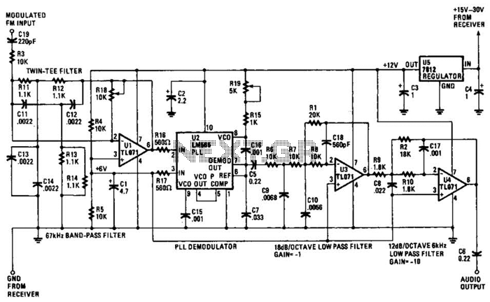
The operational amplifier (Op Amp) U1 and its associated components form a 67-kHz bandpass filter. A twin-T network, consisting of four 1100-ohm resistors and four 0.0022-microfarad capacitors, is integrated into the feedback loop of the op amp. This configuration...
A Microchip PIC12C508 8-pin CMOS microcontroller controls a night light, turning it on and off at preset times every day. It is designed to save energy, produce no electromagnetic interference (EMI), and operate without batteries, featuring a built-in lamp...
Several RS232 transceiver circuits are used for communication between microcontrollers and other devices, such as PCs or RS232 devices. This document presents a collection of well-known RS232 transceiver circuits. The circuit utilizes the MAX232 from Maxim's devices, which is...
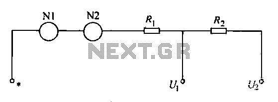
A voltmeter operates through a measuring mechanism in a specified circuit, utilizing a moving coil in series with additional resistance. The fixed coil is denoted as N1, while the moving coil is designated as N2. The additional resistances are...
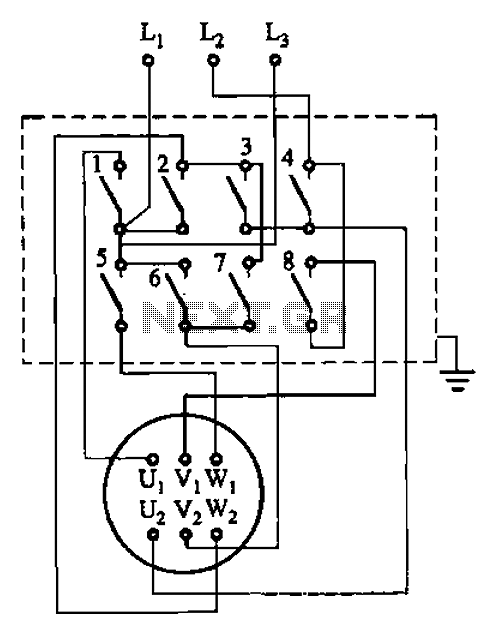
The circuit illustrated in Figure 3-36 includes the starter contact closure detailed in Table 3-1. In the figure, U1, V1, W1, and U2, V2, W2 represent the first three-phase stator windings of the motor terminals. The circuit depicted in Figure...
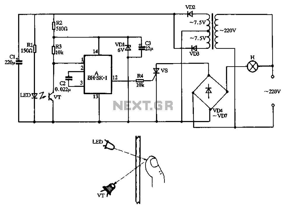
The non-contact infrared lamp switch circuit produced by BH-SK-I, as depicted in Figure 3-42, primarily consists of voice integrated circuits, an infrared light-emitting diode (LED), and a receiving tube. It includes a triac circuit and a power circuit. When...