
Desheng R-202T type two-band radio circuit diagram

The Desheng R-202T is a two-band radio receiver designed to operate on both AM and FM frequencies. The circuit typically includes several key components that facilitate the tuning and reception of radio signals.
At the core of the circuit is the radio frequency (RF) section, which comprises an RF amplifier, a mixer, and a local oscillator. The RF amplifier enhances the strength of incoming signals, while the mixer combines the amplified RF signal with a signal from the local oscillator to produce an intermediate frequency (IF) signal. This IF signal is then processed by the IF amplifier, which further amplifies it to ensure clear audio output.
The tuning mechanism usually involves a variable capacitor or an inductor, allowing the user to select the desired frequency band. The circuit may also include a band switch that enables the user to toggle between AM and FM modes.
Audio processing is handled by a demodulator, which extracts the audio signal from the IF signal. The demodulated audio is then sent to an audio amplifier, which drives the speaker or headphone output, providing audible sound to the user.
Power supply components, such as voltage regulators or battery connections, ensure that the circuit operates efficiently across different voltage levels. Additionally, various passive components, including resistors and capacitors, are used for filtering and stability.
Overall, the Desheng R-202T circuit diagram exemplifies a straightforward yet effective design for a two-band radio receiver, enabling users to enjoy a wide range of broadcasts across AM and FM frequencies.Desheng R-202T type two-band radio circuit diagram as follows:
Related Circuits
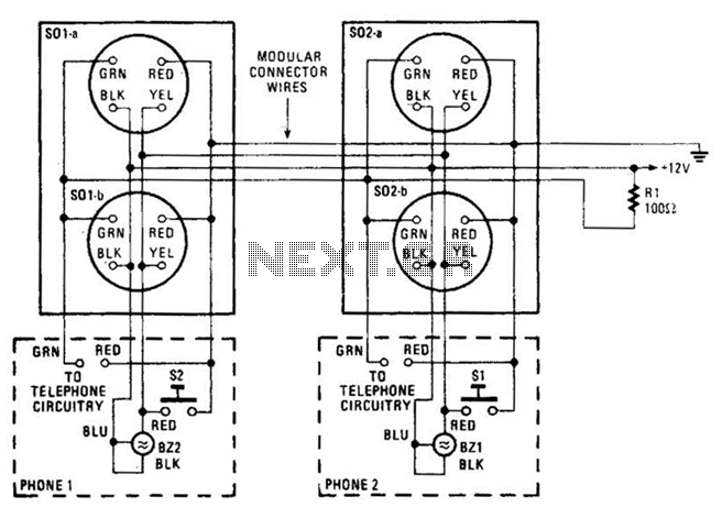
An intercom utilizing dual-modular wall jacks is depicted in this circuit. If the wires are accessible in the home telephone cable, this system can be installed with minimal difficulty. The intercom system described employs dual-modular wall jacks, which are standard...
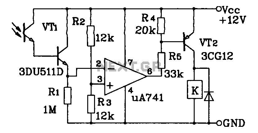
This circuit application utilizes a Darlington phototransistor for light-triggered switching. The design incorporates a Darlington phototransistor and an operational amplifier (op-amp), allowing the circuit to respond to very faint light levels. The circuit can be modified to trigger in...
The circuit diagram presented illustrates the MC14093B Fluid Level Sensor Circuit. It is characterized by its compact and simple design, utilizing a single-chip configuration suitable for a wide range of applications. The MC14093B is a CMOS quad two-input NAND gate...
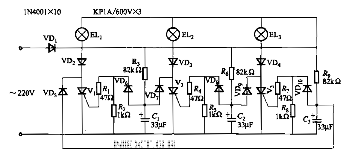
The circuit operates with a 220V mains supply through a diode (VDi) configured as a half-wave rectifier. Capacitors C1 to C3 are charged, and due to the lack of full synchronization in the charging process, a pilot thyristor is...
This circuit is a square wave oscillator that utilizes CMOS-type logic inverters. The term "logic inverter" is used to prevent confusion with a DC/AC inverter. The oscillator's output is connected to a drive circuit via the logic inverters. The...
Here is a simple radio that is easy to build and inexpensive. In fact, you probably have all the parts you need in your junk box. You'll be surprised at the great reception with this little set. More: The...