
Detecting and locating RF bugs

The proposed circuit for detecting RF transmitters is based on a superheterodyne receiver architecture, which is well-suited for the specified frequency range. The circuit consists of several key components: an antenna, a low-noise amplifier (LNA), a mixer, an intermediate frequency (IF) amplifier, and a demodulator.
The antenna is designed to capture RF signals from the environment. It should be capable of receiving signals across the 100 MHz to 3000 MHz range, which may require a broadband design or a series of tuned antennas for optimal performance. The LNA amplifies the weak RF signals received by the antenna, ensuring that subsequent stages of the circuit can process these signals effectively without introducing significant noise.
Following amplification, the RF signal is fed into a mixer, where it is combined with a local oscillator (LO) signal. The mixer generates an intermediate frequency (IF) signal, which is easier to process than the original RF signal. The choice of LO frequency is critical, as it determines the IF frequency and must be selected to ensure that the resulting IF signal falls within the operational range of the subsequent IF amplifier.
The IF amplifier further boosts the IF signal, enhancing the signal-to-noise ratio. This stage is crucial for distinguishing between the desired RF signals and background noise. The amplified IF signal is then demodulated to extract the audio or data information, if applicable, or it can be processed to indicate the presence of a detected RF signal.
To provide visual feedback, the circuit may include an LED indicator or a small display that activates when RF signals are detected, alerting the user to the presence of potential surveillance devices. Additionally, the circuit can be designed to include a frequency counter or spectrum analyzer functionality, allowing users to identify the specific frequency of the detected RF signals, which can aid in locating the source of the bug.
Overall, this RF detection circuit serves as a valuable tool for identifying unauthorized surveillance devices, providing users with a means to safeguard their privacy and security. Proper consideration of component selection, circuit layout, and shielding will enhance the performance and reliability of the design, ensuring effective detection across the intended frequency range.We wrote about a phone bug in a previous post. Here`s an app note about a circuit for detecting and locating radio frequency transmitters. This design idea showcases a circuit that detects RF ""bugs,"" such as hidden wireless cameras, eavesdropping microphones, and other spying devices that emit RF frequencies in the 100MHz to 3000MHz range 🔗 External reference
Related Circuits
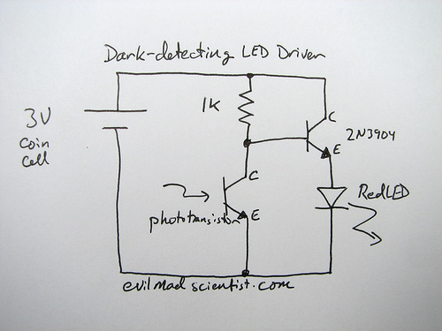
How can an LED be activated in low light conditions? This scenario, often referred to as the "nightlight problem," is applicable in various situations such as emergency lights, street lights, and even computer keyboard backlights. There are numerous solutions...
Radio transmitters for eavesdropping on private conversations and sending video pictures, battery-operated. Radio transmitters designed for eavesdropping applications typically operate within specific frequency ranges to capture audio and video signals discreetly. These devices often utilize low-power RF (radio frequency) technology...
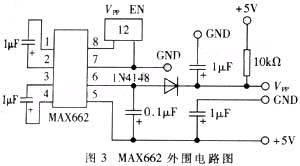
The widespread application of Flash technology in microprocessors has led to significant advancements in the development and utilization of one-chip computers. Designers have transitioned from traditional in-circuit emulators (ICE) and JTAG interfaces to more cost-effective and user-friendly development methods....
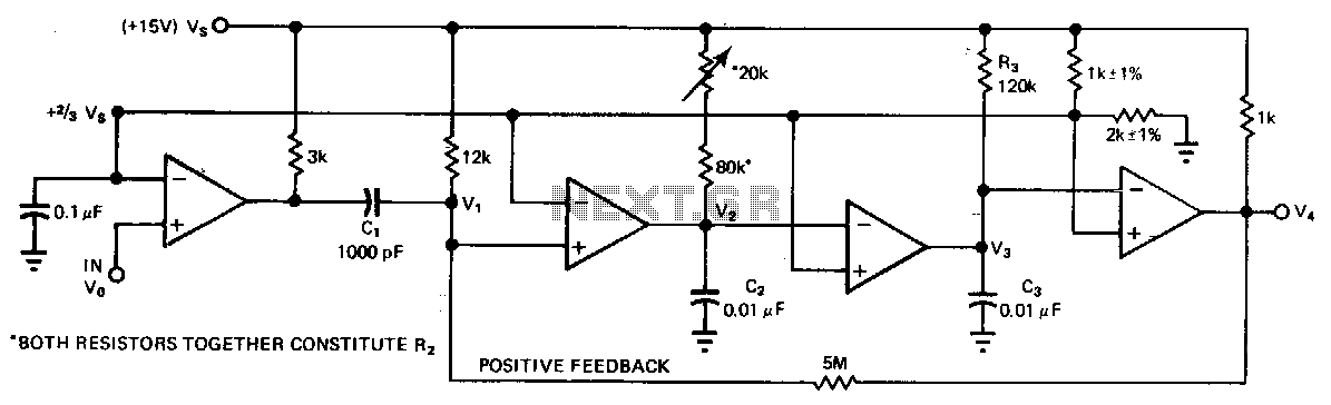
A quad comparator serves as the foundation for a frequency detector that is both faster and more cost-effective than more complex alternatives utilizing frequency-to-voltage converter chips. Positive feedback through a 5 MΩ resistor enables the circuit to detect changes...
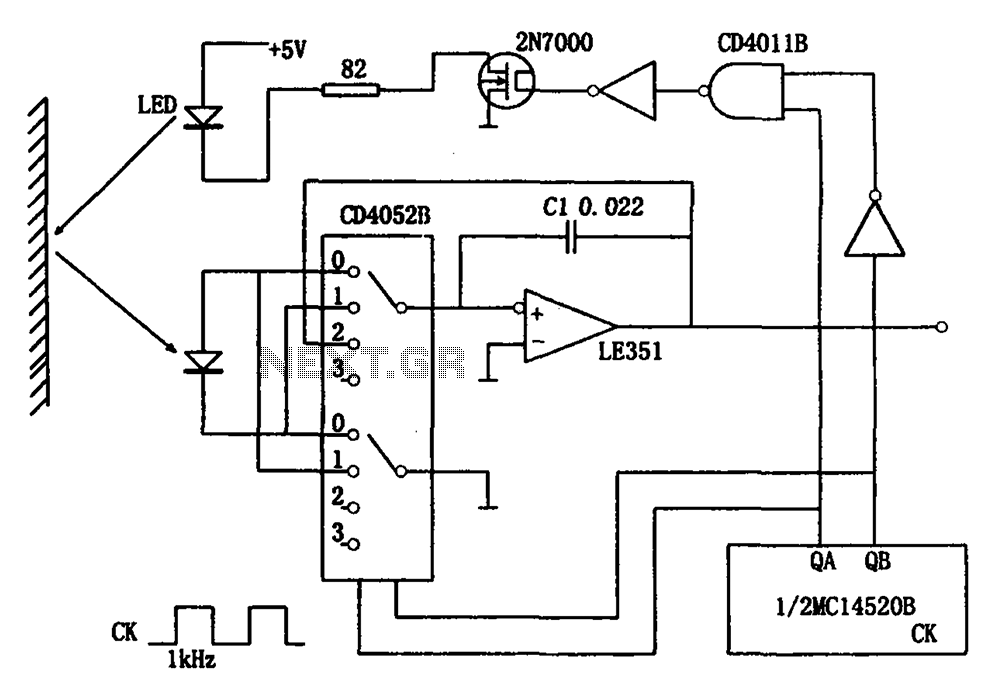
The circuit for detecting the intensity of reflected light includes infrared light-emitting diodes, photodiodes, CMOS analog switches, operational amplifiers, and other components. When the circuit operates, the infrared light-emitting diode (LED) initially remains off, allowing the photodiode to receive...

The following circuit illustrates a simple and inexpensive dark-detecting LED circuit. Features include the use of photoresistors, specifically a photocell or LDR, and an LED. This circuit utilizes a light-dependent resistor (LDR) as the primary sensing element. The LDR exhibits...