
Detection for trains on model railway

This circuit functions as a light-based detection system suitable for applications such as model railway train detection or lap counting in racing scenarios. The primary component of the system is D3, an infrared LED, which emits a beam of infrared light. This light beam is directed towards T3, a phototransistor that acts as a light sensor.
The circuit operates with a supply voltage ranging from 4.5 to 12 volts, ensuring compatibility with various power sources. The maximum load for the output is specified at 100 mA, which is critical for maintaining the integrity of the components involved.
The transistor T1, a BC 557B, is configured to provide a constant current to D3, ensuring that the infrared LED operates continuously. Resistors R1 (1 kΩ) and R2 (15 Ω) are used to limit the current flowing through the circuit, protecting the components from excessive current that could lead to damage.
When the light beam emitted by D3 is uninterrupted, the base of transistors T2 (BC 547B) and T3 (104 BP) is effectively grounded, preventing T2 from conducting. As a result, the output LED (D4, a red LED) remains off. However, when the beam is interrupted—such as when a train passes through the detection zone—T3 begins to conduct, allowing current to flow through T2. This conduction activates the output LED, signaling the detection event.
Additional components include diodes D1 and D2 (1N4148), which are used for protection against reverse polarity and to ensure the stability of the circuit. Resistor R3 (10 kΩ) and R4 (220 Ω) are also strategically placed to assist in biasing the transistors and controlling the current flow within the circuit.
Overall, this light valve detection circuit is designed for simplicity and reliability, making it an effective solution for detecting moving objects in model railways or competitive racing environments.This light valve can be used for example to detect trains on model railway or a lap counter at the close racing. D3 receives a constant stream of power built around T1. When the light beam from D3 to T3 is not interrupted, led T3 and T2 is the basis of practically grounded.
T2 not conduct and the LED is not lit. When the beam is interrupted, spert T3 and T2 conducts and the LED will light. Of course listen to other things like LED control between plus and the collector of T2. Please note the maximum load of 100 mA. The supply voltage may be between 4.5 and 12 volts. R1 = 1 kW R2 = 15 ? R3 = 10 k R4 = 220 ? D1, D2 = 1N4148 D3 = infrared LED D4 = LED red T1 = BC 557B T2 = BC 547B T3 = 104 BP 🔗 External reference
Related Circuits
This manual applies to all integral horsepower DC motor controls within this series, ranging from 40 HP to 300 HP. The integrated circuit regulator selection of these DC motor controls is modular in construction, allowing for minimal downtime in...
The following is a method to allow day and night detection using Infrared/Visible light sensitive phototransistors and a simple LM339 voltage comparator circuit. A phototransistor is mounted between the rails so that it is covered by the train as...
The SP1481E, SP1485E, SP1490E, and SP1491E series transceivers, combined with the SP6652 high-efficiency, high-frequency current mode PWM buck regulator, facilitate the creation of an isolated RS-485 interface capable of providing up to 2kVrms isolation. This configuration supports CAN communication...
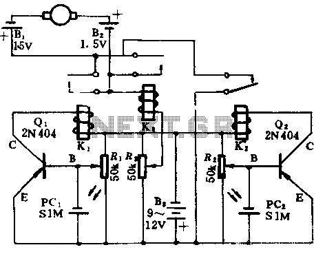
In the absence of light, photocells PC1 and PC2 exhibit high resistance, causing transistors Q1 and Q2 to remain off, which prevents the relay contacts K1 and K2 from closing. The battery B3 is connected through a potentiometer Rs,...
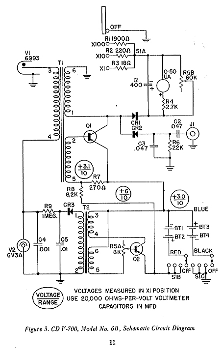
This is the schematic for the 6A model located at the bottom of the unit, which is incorrect. These units have been subjected to movement for over 40 years, leading to many bottoms being swapped due to battery corrosion...
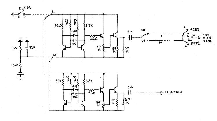
Each line key has three positions. In the centralized position, it connects the line circuit to the line to await a call. In the downward position (KK), it operates a K relay which switches the line through to the...