
Victoreen Model CD V-700 Schematic Diagram

The schematic and repair process of the 6B Geiger Counter highlights critical considerations in the maintenance of vintage electronic devices. The incorrect schematic, specifically for the 6A model, illustrates the challenges faced when dealing with decades-old equipment where components may have been mixed or replaced over the years. The corrosion and tarnishing of transistor leads emphasize the importance of proper manufacturing practices, particularly the use of solderable materials for component leads. The failure of solder joints due to tarnishing can lead to intermittent or complete circuit failure, necessitating thorough inspection and rework.
During the repair process, the removal of the PC board allowed for detailed visual inspection, revealing not only the condition of the leads but also the quality of the solder joints. The use of photographic documentation serves as a practical approach in complex repairs, enabling accurate reassembly without the need for intricate drawings. The repair methodology, which involved scoring and tinning the leads, is a critical skill in electronics repair, particularly for older components that may not adhere to modern manufacturing standards.
The addition of a piezoelectric transducer not only restored functionality but also enhanced the user experience by providing audible feedback. This modification reflects the adaptability required in electronics repair, allowing for the integration of contemporary components into legacy systems. Overall, the experience underscores the necessity for meticulous inspection and the application of proper soldering techniques to ensure the longevity and reliability of electronic devices, particularly those with historical significance.This is the 6A schematic that was in the bottom of the unit. It is incorrect. These units have been banging around for over 40 years. Many bottoms have been switched around, due to battery corrosion in the lower case. My Geiger Counter is a 6B, and the schematic on the bottom is a 6A. When I was tracing the circuit, this drove me nuts, until I fig ured out what had happened. The annoying schematics do not give the Model #. This is a horrendous oversight in the documentation world. But then, the manufacturer never figured that the bottoms from 4 other types of radiation detectors would be switched around like crazy, over a 45 year period. The unit was DOA. Step 1 was to pull the PC board, and start checking things. Rather than take the time to make a tedious drawing, I simply took a photo, so it is easy to re-solder the wires back afterwards.
I spent 10 years as an electronics technician, and 20 more as a semiconductor engineer. Many problems can be found simply by visual inspection, if you know what to look for, and this case was no exception. I measured the two diode junctions of the 2 transistors in the unit, and they looked fine. But close inspection revealed that the leads of the transistors were NOT SOLDERABLE when the unit was made.
Four of the 6 transistor leads were tarnished beyond belief, WHEN INSTALLED, 44 years ago. The result was that over time, the lousy solder joints ceased being electrically connected. Not only can the tarnished leads be seen by inspection, but the solder did not form a proper fillet. The solder did not "wick-up" the leads, resulting in an extremely poor solder joint. Historically (1960`s), some transistor leads were NEVER properly plated with an easily solderable alloy, and many were plated with nickel, which hates to be soldered. For proper soldering, the leads of a device must be "tinned". That means that they have had a shiny coat of solder applied to the surface, BEFORE any attempt is made to solder them into a circuit.
This was certainly not done here. My solution was to remove the transistors, and score the leads by squeezing and pulling on them with a small pair of serrated long nose pliers, until you see bare metal. Then tin the leads, and reinstall. Worked like a champ. This must be done carefully, as the transistor pads are too small, and the holes are way too big. Use a perfectly tinned soldering iron, and retract it quickly after the melt, or the traces will lift right up.
I`m an expert at this stuff, and two pads lifted off the board anyway - I must be losing my touch. WHAT`S the point The point is that there are many thousands of units out there, which were probably assembled with the same "un-solderable lead" transistors. Not to mention the "piling on" of excess solder, which masks the poor connections underneath. I removed a lot of solder from various joints with a "solder-sucker", so I could inspect the underlying wires.
My next move was to install a piezoelectric transducer from Radio Shack, so I could listen to the clicks. I removed the obsolete headphone connector, added two drops of super glue, and 2 solder joints, and I had sound!
Pretty cool. Here is a summary of Model Numbers, with corresponding dates of production. Anton, Chatham, Electro-Neutronics, International Pump, Lionel, Nuclear Measurements, and Universal Atomics GM units are included. 🔗 External reference
Related Circuits

Useful circuit for self-powered speakers, radios, and TVs; can be used as a car power amplifier. Here is the schematic for an 8-watt audio power amplifier. The described circuit serves as an 8-watt audio power amplifier, suitable for various applications,...

Darlington phototransistor type light-sensitive switch control circuit application. The Darlington type phototransistor serves as a sensitive element, capable of detecting low light levels for the detection of reflected light signals. The Darlington phototransistor circuit utilizes a pair of transistors configured...
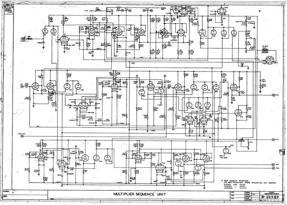
A hard copy schematic diagram pertaining to the computer CSIRAC. This diagram illustrates the intricate connections among all the components within the circuit. Such diagrams were utilized for circuit construction and subsequent testing. In the case of CSIRAC, the...
Here's how you can make an electronic speed controller (ESC) for your remote control car, boat, or even an airplane using an old servo and some MOSFETs. Please note that this ESC has a very limited control range. Meaning...

The RTD temperature sensor, as illustrated in the subsequent figure, collects temperature data from the field. This data is converted into a voltage signal by the XTR105, which is then transformed into a 4 to 20 mA current output....

The circuit features a dual time base using a 556 timer, which comprises two synchronized multivibrators and two output clock signals. The output signals are synchronized with defined intervals, and the oscillation frequency can be adjusted by varying the...