
Detection systems in PET

Compton scattering and photoelectric absorption produce electrons with different energy distributions. In photoelectric absorption, all photon energy is transferred to the electron, resulting in a sharply peaked energy distribution near the incident photon energy. In contrast, Compton scattering leads to recoil electrons with a range of energies, which depend on the scattering angle. The energy of the recoil electron can be expressed by a specific equation, where q represents the photon scattering angle, E_b is the electron energy, E is the incident photon energy, and E_g is the energy of the scattered photon. The maximum energy for 511 keV photons occurs at a scattering angle of π, yielding a value of 340.7 keV.
When real scintillation detectors are exposed to mono-energetic photons, the measured energy does not correspond to the initial electron's energy but rather to the total energy deposited by the photon in the detector. This distinction is significant as photons that initially interact via Compton scatter may engage in additional interactions within the detector. In sufficiently large detectors, most Compton-scattered photons will ultimately deposit all their energy, leading to most events registering in the photon energy peak. In these cases, the energy distribution is more accurately described by the term "full-energy peak" rather than "photo-peak." Conversely, in smaller detectors, photons may escape after depositing only a portion of their energy in the crystal, resulting in a measured energy distribution that aligns more closely with a different representation.
The energy distribution is further complicated by the finite energy resolution of the detector system and the fact that the incoming radiation is not mono-energetic; some photons will have experienced Compton scattering prior to detection. Additional events may register with energy exceeding the full-energy peak due to photon interactions occurring close together in time, preventing them from being resolved as separate events. The energy resolution of the system is defined as the ratio of the full-width at half-maximum (FWHM) of the full-energy peak to the energy value at the maximum of the full-energy peak. If a significant proportion of incident photons register in the full-energy peak and the detector system exhibits good energy resolution, it becomes feasible to discriminate against events arising from photons scattered within the object by rejecting those with lower measured energy. The proportion of events in the full-energy peak tends to increase with larger detector sizes; however, larger detectors may compromise the spatial resolution of the system. The number of events in the full-energy peak can also be enhanced by optimizing various parameters within the detection system.Detection systems are a key component of any imaging system, and an understanding of their properties is important for establishing appropriate operating criteria or designing schemes for obtaining quantitative information. In this section scintillation detection systems, which are used in the majority of PET tomographs, are discussed.
The scintil lation process involves the conversion of high-energy photons into visible light via interaction with a scintillating material, and consists of the following steps: In a scintillation detector, the scintillator is optically coupled to a photomultiplier tube (PMT) which then generates an electrical signal in response to light incident upon its face. There are several variations on this theme which are used in PET - for example, a 2D array of crystals may be coupled to 4 PMTs (the block-detector, Casey and Nutt, 1986 ), an array of PMTs may be coupled to a single planar crystal (the Anger camera, Anger, 1958 ), or an array of crystals may be coupled to a multi-channel PMT ( Cherry et al 1997 ).
Compton scatter and photo-electric absorption generate electrons of differing energy distributions. In photo-electric absorption, all the photon energy is transferred to the electron, and the energy distribution of the photo-electrons is sharply peaked close to the energy of the incident photon. In Compton scatter, the recoil electrons have a range of energies, depending on the scattering angle.
From equation 1 we can say that the energy of the recoil electron will be where q is the photon scattering angle, Ebis the energy of the electron, E is the energy of the incident photon and EG is the energy of the scattered photon. Ebreaches a maximum when q = p. For 511 keV photons, this value is 340. 7 keV. A typical energy distribution for electrons involved in interactions with 511 keV photons is shown in figure 17.
When real scintillation detectors are exposed to mono-energetic photons, the energy measured is not that of the electron generated by the initial interaction, but rather the total energy deposited by the photon in the detector. This distinction is important because photons initially interacting by Compton scatter may subsequently be involved in further interactions within the detector.
In a sufficiently large detector, most Compton-scattered photons will eventually deposit all their energy, and most events will register in the photon energy peak. Under these circumstances, this feature of the energy distribution is better described by the term "full-energy peak" rather than "photo-peak".
In small detectors, photons may escape after depositing only part of their energy in the crystal, and the measured energy distribution is closer to that shown in figure18. In practice, the energy distribution is also blurred by the finite energy resolution of the detector system, and by the fact that the incident radiation is not mono-energetic, as a proportion of the photons will have undergone Compton scatter prior to detection.
There will also be some events with energy greater than the full-energy peak, where photon interactions with the detector occur sufficiently close together in time that they cannot be resolved as separate events. The energy resolution of the system is defined as the ratio of the full-width at half-maximum (FWHM) of the full energy peak and the energy value at the full energy peak maximum.
If a large proportion of the incident photons register in the full-energy peak and the energy resolution of the detector system is good, then it is possible to discriminate against events arising from photons scattered within the object by rejecting those with a low measured energy. As discussed above, the proportion of events in the full-energy peak increases with increasing detector size.
However, large detectors reduce the spatial resolution of the system. The number of events in the full-energy peak can also be increased by inc 🔗 External reference
Related Circuits
The power-supply controller features staggered voltage-output sequencing. Four voltage outputs are activated simultaneously for voltage tracking; two outputs are designated for core and I/O supplies during power-up, while the other two outputs cater to line driver supplies where tracking...

The design of solar panel systems with a lead-acid buffer battery is typically configured to ensure that the battery remains charged even during periods of limited sunlight. Solar panel systems integrated with lead-acid buffer batteries are designed to optimize energy...
In certain Phase-Locked Loop (PLL) applications, it is often necessary to provide a lock indication when the PLL is in a locked state. The simplest method for this indication is a binary signal, represented as either 0 or 1. In...
The SP1481E, SP1485E, SP1490E, and SP1491E series transceivers, combined with the SP6652 high-efficiency, high-frequency current mode PWM buck regulator, facilitate the creation of an isolated RS-485 interface capable of providing up to 2kVrms isolation. This configuration supports CAN communication...
When the sensor detects movement in a room it will take a burst of 10 photos with the digital camera. Each photo is taken at 0.5sec interval. After the 10 photos, the camera waits 3 seconds for further movement...
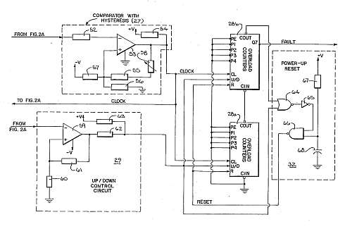
This motor overload circuit allows for short-term overdriving of a system, which is dependent on heat buildup. An overload detection circuit safeguards the motor against currents exceeding the rated current for specific exposure durations. The permissible exposure times are...