
PLL Lock Detection

In PLL circuits, a lock indication serves as an essential feedback mechanism, confirming that the output frequency of the voltage-controlled oscillator (VCO) is synchronized with the reference frequency. This synchronization is crucial for ensuring that the PLL operates correctly and that the output signal meets the desired specifications.
To implement a binary lock indication, a simple logic circuit can be employed. This circuit typically consists of a comparator that monitors the phase difference between the reference signal and the VCO output. When the phase difference falls within an acceptable range—indicating that the PLL is locked—the comparator outputs a high signal (1). Conversely, if the PLL is not locked, the output will be low (0).
In practical applications, the binary output can be used to drive an LED indicator, which visually represents the lock status. Additionally, this signal can be interfaced with microcontrollers, allowing for further processing or integration into larger systems.
For more sophisticated applications, additional indicators may be incorporated, such as a multi-state LED or a graphical display, which can provide more detailed information about the PLL's performance, including lock time and phase error. However, for basic applications, the binary indication remains a straightforward and effective solution to signal the locked state of a PLL.In some PLL application, sometimes we need to provide lock indication when the PLL is in locked state. The simplest one is binary indication, 0 or 1 to. 🔗 External reference
Related Circuits

The concept involved removing the center page from a magazine and cutting it into four pieces to create a card suitable for a filing system. The front side of each card provided connections to the integrated circuit (IC), while...
The objective was to modify this radio for functionality on the 70cm amateur radio band. However, this attempt failed because the voltage-controlled oscillator (VCO) did not oscillate at the required frequencies for 70cm operation, as the VCO control voltage...

This is a programmable clock timer circuit that utilizes individual LEDs to indicate hours and minutes. Twelve LEDs are arranged in a circle to represent the 12 hours of a clock face, while an additional 12 LEDs are positioned...
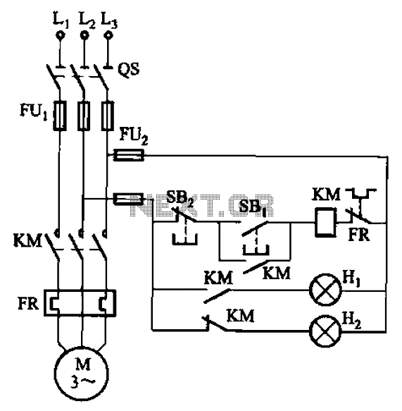
The circuit illustrated in FIG. 3 + 20 features SBi as the start button, SB2 as the stop button, Hi for run lights, and Hz for down lights. The subsequent circuit description aims to prevent tediousness by omitting the...
This month's project is based on the 4017 chip that was used in a previous project. It is advisable to review the fundamentals of the 4017 chip as presented in last month's project. The circuit has been modified slightly;...
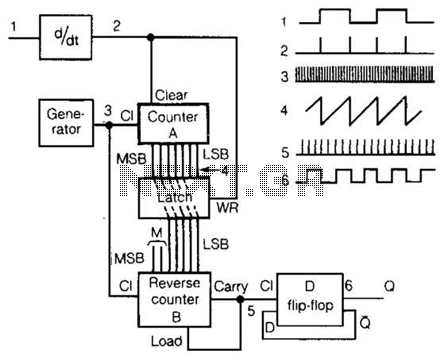
An input rectangular signal is differentiated to produce short impulses from its edges. These impulses transfer the content of counter A to a latch that clears the counter after a very brief period. Counter A counts impulses at a...