
Detector Components & Infrared Motion Work

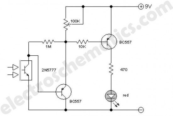
The electronic circuit schematic for an infrared motion detector typically consists of several key components that work together to detect motion through infrared radiation. The primary elements include an infrared (IR) sensor, a microcontroller or comparator circuit, a power supply, and output devices such as alarms or lights.
The IR sensor is the heart of the motion detection system. It detects infrared radiation emitted by objects, particularly warm bodies like humans or animals. The sensor generates a voltage signal when it detects a change in infrared levels, indicating motion within its field of view.
This signal is then fed into a microcontroller or comparator circuit, which processes the input from the IR sensor. The microcontroller can be programmed to differentiate between normal environmental changes and actual motion. It can also be configured to adjust sensitivity levels, set time delays for the output activation, and manage other parameters for optimal performance.
The power supply provides the necessary voltage and current to the entire circuit, ensuring that all components operate effectively. Typically, a battery or a regulated power source is used, depending on the application and location of the motion detector.
Output devices, such as LEDs, buzzers, or relays, are connected to the microcontroller. When motion is detected, the microcontroller activates the output device to signal the presence of motion. This may involve lighting up an LED, sounding an alarm, or triggering a camera or other security devices.
The wiring diagram for such a circuit would illustrate the connections between the IR sensor, the processing unit, the power supply, and the output devices. Proper attention to component specifications and circuit layout is crucial to ensure reliable operation and minimize false triggers. The schematic should also include any necessary resistors, capacitors, and other passive components required for signal conditioning and stabilization.Detector Components & Infrared Motion Work, Electronic Circuit Schematic Wiring Diagram, Detector Components & Infrared Motion Work. 🔗 External reference
Related Circuits
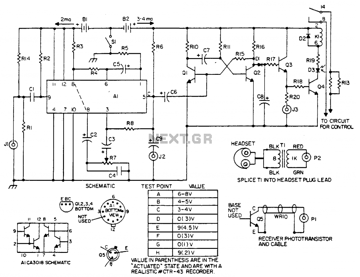
The laser light detector employs a sensitive phototransistor (Q5) positioned at the focal point of a lens (LE2). The output from Q5 is directed to a sensitive amplifier composed of an array (A1), which is biased through a voltage...
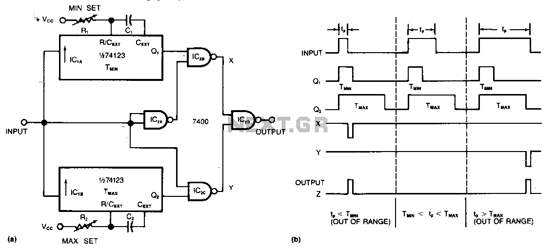
This circuit requires only two integrated circuits (ICs) to monitor a train of positive pulses and produces a single positive output pulse for each input pulse that falls outside specified duration limits. The minimum and maximum limits can be...
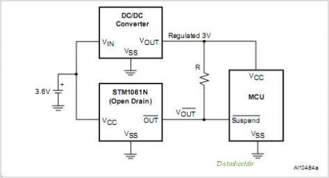
STMicroelectronics introduces the STV0288, its latest DVB and DIRECTV QPSK digital receiver, which adds blind scan capability and DiSEqC 2.0 to the industry-leading STV0299 and provides a cost reduction path for new products. The STV0288 is a sophisticated digital receiver...
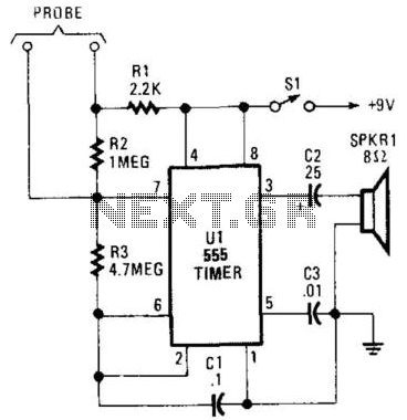
The Full-Cup Detector utilizes a 555 oscillator/timer configured to generate a 15 Hz clicking sound until its probe contacts are bridged. At that point, the output frequency increases to approximately 500 Hz. This device is designed to assist visually...
This enhanced infrared detector is designed for use with commercial infrared remote control handsets. This compact circuit is effective for quick go/no-go applications. The infrared detector circuit is engineered to respond to signals emitted by infrared remote control devices, commonly...
Implementing peak-detector circuits is straightforward with the CA3130, as illustrated in the schematic diagram of this circuit. The figure below presents the schematic diagram. The CA3130 is a high-performance operational amplifier that is well-suited for peak detection applications due to...