
DEVIATION METER

The described circuit is designed for integration into FM VHF receivers, serving as a tool for signal analysis and jamming detection. The connection point is established at the FM discriminator, a critical component responsible for demodulating frequency-modulated signals. By tapping into this point, the circuit can monitor the deviation of incoming signals.
In FM communication, each transmitted signal is characterized by a specific deviation from the carrier frequency, which is determined by the modulation of the signal. This unique deviation signature allows for the differentiation of signals even in the presence of interference. The circuit exploits this property to detect and analyze the characteristics of various signals, making it particularly useful for identifying and locating jamming sources.
The circuit may incorporate elements such as bandpass filters to isolate the desired frequency range, amplifiers to boost the signal strength, and a microcontroller or dedicated processing unit to analyze the deviation signatures. The output can be visualized through an oscilloscope or transmitted to a computing device for further analysis.
In summary, this circuit provides a robust solution for monitoring FM VHF signals, enabling users to distinguish between legitimate transmissions and potential jamming attempts based on unique deviation signatures. Its application is essential in scenarios where signal integrity is critical and interference must be identified and mitigated.You can use this circuit in most FM VHF receivers; the hookup is off the FM discriminator. Because every signal transmitted has its own deviation signature, this can be a red plusin hunting jammers 🔗 External reference
Related Circuits
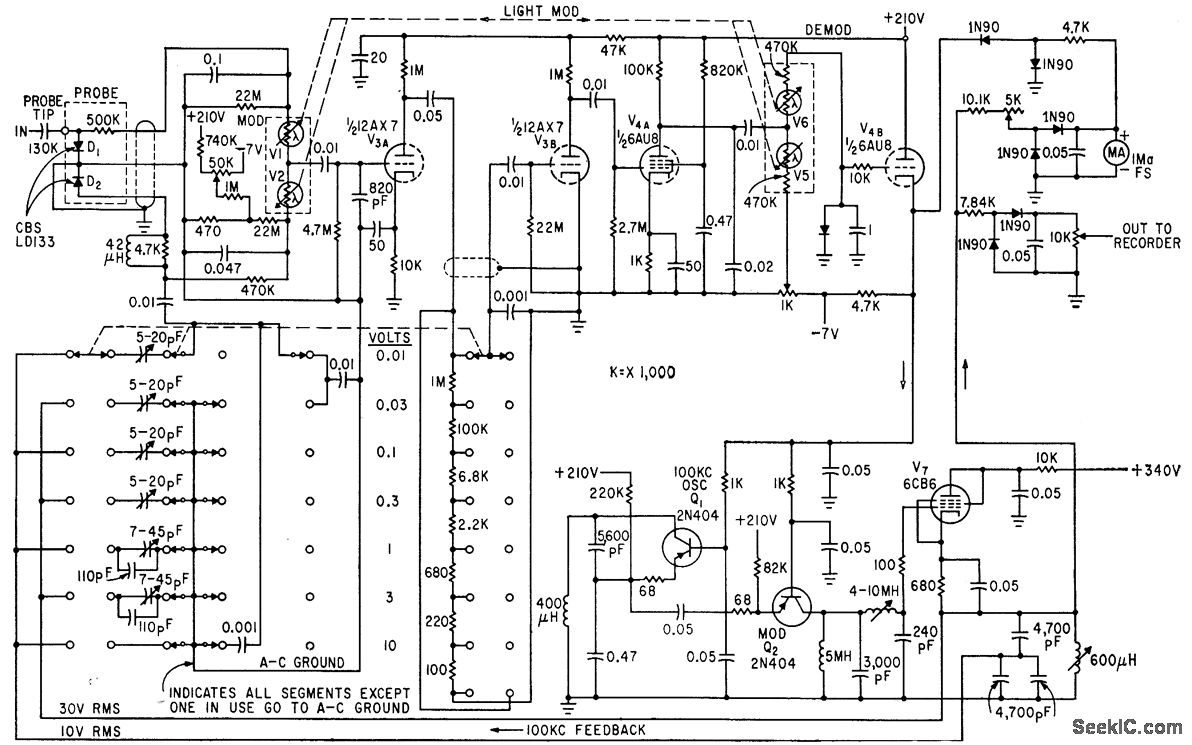
The circuit generates a low-frequency waveform with an amplitude that corresponds to an unknown RF voltage, utilizing a photochopper modulator (VI-V2) as an error detector. This arrangement provides seven voltage ranges from 10 mV RMS to 10 V RMS...
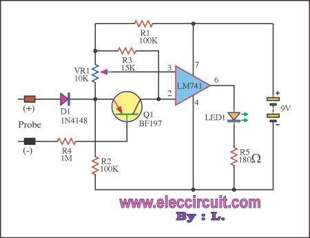
This circuit is capable of measuring voltages up to 15 volts, utilizing a 9-volt battery that draws a current of only 23 mA. The input circuit includes a diode for protection. The circuit design features a voltage measurement system that...
An electronic project to construct an LC meter project kit of exceptional accuracy to measure both inductance and capacitance—an inductance meter and capacitance meter all in one unit. It is readily available as a comparatively inexpensive kit, which is...
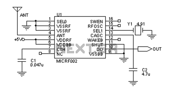
Early transmitters using LC oscillators experience significant frequency drift. The introduction of Surface Acoustic Wave (SAW) devices addresses this issue, providing substantial frequency stability comparable to crystals. These devices can achieve fundamental frequencies in the hundreds of megahertz or...
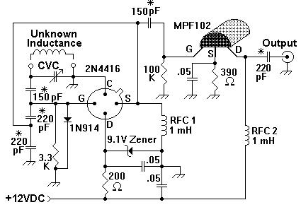
A device for measuring inductance. Over the years, articles describing devices for measuring inductance have appeared in QST and elsewhere, but none of them were suitable, so a new device has been developed. The inductance measurement device is designed to...

The low output impedance of a closed-loop operational amplifier (op amp) provides ideal immunity to line noise, while the offset voltage drift of the op amp serves as a temperature sensor. Utilizing the op amp in this manner requires...