
inductance meter

The inductance measurement device is designed to provide accurate readings of inductance values across a range of inductive components. The core of the device typically consists of an oscillator circuit that generates a high-frequency signal. This signal is applied to the inductor under test, and the resulting current and voltage waveforms are analyzed to determine the inductance.
Key components of the circuit include an operational amplifier configured as a voltage comparator to measure the phase shift introduced by the inductor. A microcontroller or digital signal processor (DSP) can be used to process the signals and calculate the inductance based on the frequency response. The device may also incorporate a display module, such as an LCD or LED, to present the measured inductance value to the user.
Furthermore, a user interface comprising buttons or a touchscreen could allow the operator to select different measurement ranges or modes, enhancing the functionality of the device. Calibration features may also be included to ensure accuracy across a wide range of inductance values.
Power supply considerations are crucial, with options for battery operation or external power sources. Proper filtering and decoupling capacitors should be implemented to minimize noise and ensure stable operation of the measurement circuit.
Overall, this inductance measurement device represents a comprehensive solution for hobbyists and professionals alike, offering precision and versatility in the evaluation of inductive components.A device for measuring inductance Over the years, articles describing devices for measuring inductance have appeared in QST, and elsewhere, but none of them were just right for me, so I have developed .. 🔗 External reference
Related Circuits
The circuit utilizes two quad voltage comparators (LM339) to illuminate a series of eight LEDs that indicate volume levels. Each of the eight comparators is set to specific bias voltages determined by a voltage divider, allowing the lower right...
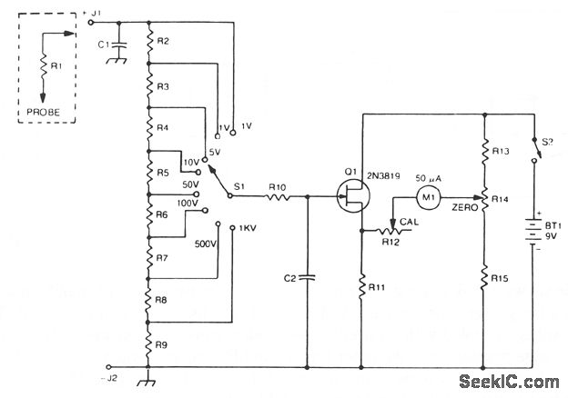
The 2N3819 FET serves as a solid-state voltage output meter (VOM). In this configuration, the 2N3819 functions as a cathode follower. The bias offset, or meter null, is achieved using resistors R14 and R12, while the full-scale calibration is...
This simple LED VU meter has only a few parts but is useful as an indicator for the noise. The circuit is built around an LM3915, the brother of the logarithmic LM3914. The input signal from the VU meter...
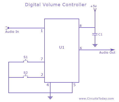
A digital volume control circuit diagram utilizing the DS1669, a potentiometer integrated circuit. This circuit can serve as a digital volume controller for audio amplifiers and various other applications. The digital volume control circuit employs the DS1669 integrated circuit, which...
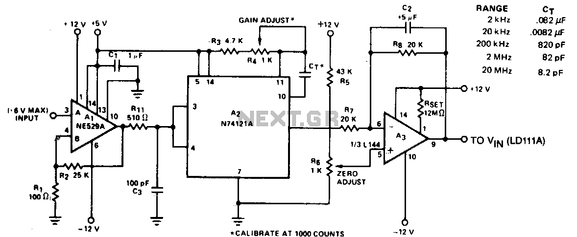
The circuit converts frequency to voltage by taking the average DC value of the pulses from the 74121 monostable multivibrator. The one-shot is triggered by the positive-going AC signal at the input of the 529 comparator. The amplifier functions...
This digital thermometer indicates the temperature measured with an NTC using 7 LEDs. The circuit works using an opamp, the well-known 741, which amplifies the voltage difference between its plus and minus input. This amplification (sensitivity) can be set...