
RF VOLTMETER

The described circuit employs a photochopper modulator as a key component for detecting RF voltage levels. By converting the RF signal into a low-frequency waveform, the circuit enables precise measurements of low-level RF voltages. The use of a photochopper allows for effective isolation and modulation of the RF signal, which enhances the accuracy of the error detection process.
The circuit operates within specified voltage ranges, providing flexibility for various applications. The seven selectable voltage ranges allow for measurements from 10 mV RMS, suitable for detecting weak signals, to 10 V RMS, accommodating stronger RF voltages. This adaptability is crucial for applications that require precise measurement across a wide dynamic range.
The frequency response of the circuit is noteworthy, extending from 500 kHz to 1,000 MHz. This broad frequency range ensures that the circuit can effectively measure RF signals across a variety of communication and broadcasting applications, making it suitable for both laboratory and field use.
Overall, the combination of a photochopper modulator for error detection, along with the wide voltage and frequency ranges, results in a robust and versatile circuit for measuring low-level RF voltages. This design is particularly beneficial in electronics and telecommunications, where accurate measurement of RF signals is essential for system performance and reliability.Circuit generates low-frequency waveform whose amplitude is equivalent to that of unknown r-f voltage, using photochopper modulator VI-V2 as error detector. Arrangement gives seven voltage ranger from 10 my rms to 10 v rms full scale, over frequency range of 500 kc to 1, 000 Mc.
-T. C. Anderson, Measuring Low-Level R-F Voltage with Servo Feedback Te chniques, Electronics, 34:28, p 63-65. 🔗 External reference
Related Circuits

This is a low-power voltmeter circuit designed for use with alternative energy systems operating on 12V and 24V batteries. The voltmeter features an expanded scale that displays small voltage increments within the 10 to 16V range for 12V batteries...
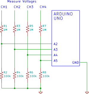
A four-channel voltmeter that displays voltage readings in a software application running on a computer. An Arduino reads the voltages and sends them to an application written in the Processing language. The described circuit comprises a four-channel voltmeter system that...
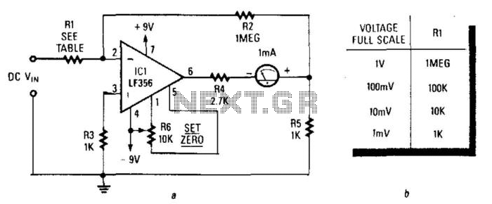
An LF356 operational amplifier is utilized as a gain amplifier, with the output taken across resistor R5. When a full-scale current of 1 mA flows through the meter, a voltage of exactly 1 V appears across R5, which should...
This is an easy-to-build yet highly accurate digital voltmeter designed as a panel meter for use in DC power supplies or any application requiring precise voltage indication. The circuit utilizes the CL7107 ADC (Analog to Digital Converter) IC manufactured...
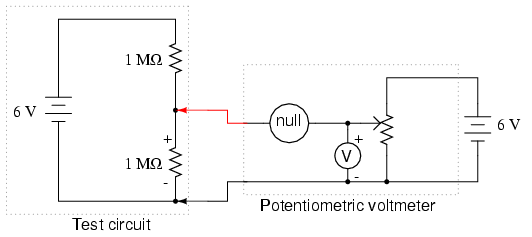
The potentiometer value is not critical; any value from 1 kΩ to 100 kΩ is acceptable. If the "precision potentiometer" described earlier in this chapter has been constructed, it is recommended for use in this experiment. The actual values...
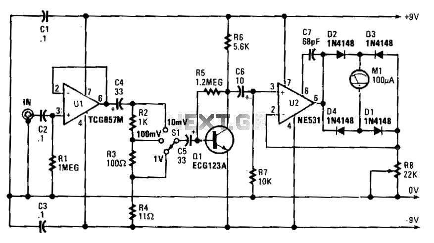
Capacitor C4 couples the output of U1 to a simple attenuator, which provides a loss of 0 dB, 20 dB, or 40 dB, depending on the setting of range switch S1. The circuit's sensitivity is 10 V rms for...