
Differential Temperature Sensor

The differential temperature sensor circuit typically consists of two temperature sensing elements, such as thermocouples or thermistors, positioned in separate locations. These sensors generate voltage outputs that are proportional to the temperature of their respective environments. The circuit is designed to amplify the difference in voltage between the two sensors, effectively providing a measurement of the temperature differential.
In a typical configuration, the outputs from the temperature sensors are fed into a differential amplifier. This amplifier is configured to subtract one voltage from the other, allowing for precise measurement of the temperature difference. The gain of the amplifier can be adjusted to ensure that the output signal is within a usable range for further processing or display.
Additional components may include resistors for biasing, capacitors for filtering noise, and possibly a microcontroller or analog-to-digital converter (ADC) for digital output. The output from the differential amplifier can be displayed on an LCD or sent to a data acquisition system for monitoring and analysis.
The schematic diagram would illustrate the connections between the sensors, the differential amplifier, and any additional circuitry necessary for the operation of the sensor system. Proper layout and component selection are critical for minimizing errors due to noise and ensuring accurate temperature measurements.Differential temperature sensor is used to measure temperature difference in two different area. Here is the schematic diagram of the circuit: Please note.. 🔗 External reference
Related Circuits
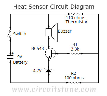
This simple heat sensor circuit can detect heat from various electronic devices such as computers and amplifiers, generating a warning alarm when overheating occurs. It can also sense heat from the environment, but it is primarily designed for use...
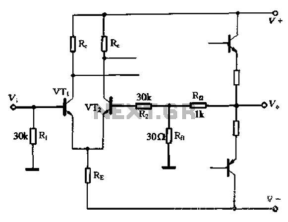
The circuit utilizes the configuration illustrated in Figure 1-36, with the feedback circuit and bias circuit implemented separately. The feedback resistor, Rfl, is approximately 30 ohms. To maintain the desired amplification, the resistor R queue is set to 1...

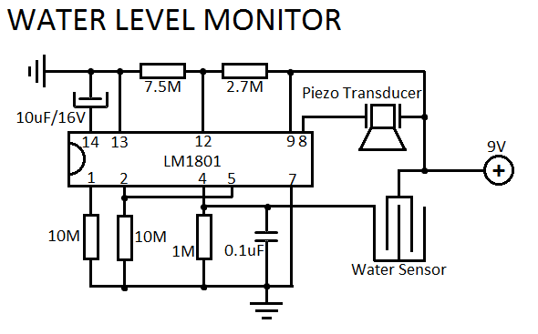
LM1801 Water Level Sensor Circuit Diagram. Features: reference voltage is overshot, and the IC drives the ceramic transducer to beep, low power consumption. The LM1801 water level sensor circuit utilizes the LM1801 integrated circuit, which is designed to monitor water...
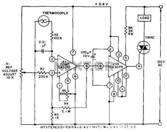
This control, featuring zero-voltage load switching, utilizes a CA3130 BiMOS operational amplifier and a CA3079 zero-voltage switch. The CA3130, functioning as a comparator, is particularly suited for comparing the low voltages produced by a thermocouple against an adjustable reference...
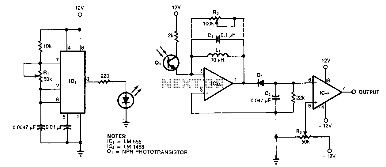
A resonance-tuned narrow-band amplifier enhances the optical object detector's resistance to stray light. The components C1 and L1 within the feedback loop of IC2A enable the operational amplifier to transmit only those frequencies that are at or near the...
This simple water level sensor circuit monitors the presence of water in a specific location or container. The circuit activates an acoustic alarm when it detects water. The water level sensor circuit typically consists of several key components, including a...