
Thermocouple Temperature Control

The circuit employs a CA3130 BiMOS operational amplifier, which is characterized by its high input impedance and low offset voltage, making it well-suited for applications involving low-level signals like those from a thermocouple. The operational amplifier is configured as a comparator, allowing it to efficiently compare the voltage output from the thermocouple with a user-defined reference voltage.
The adjustable reference voltage is set within the range of 0 to 20 mV, enabling the circuit to accommodate various thermocouple outputs, which are typically low. This flexibility is essential in applications where precision temperature measurement is critical. The output of the CA3130 indicates whether the thermocouple voltage exceeds the reference voltage, thus triggering the CA3079 zero-voltage switch.
The CA3079 is designed for zero-voltage switching, which minimizes switching transients and electromagnetic interference, enhancing the reliability of the control circuit. This switch allows for the load to be turned on or off without generating significant voltage spikes or noise, which is particularly beneficial in sensitive electronic systems.
Overall, this control circuit provides an effective solution for temperature monitoring and control applications, ensuring accurate voltage comparison and reliable load switching while maintaining signal integrity and minimizing disturbances. This control, with zero-voltage load switching, uses a CA3130 BiMOS op amp and a CA3079 zero-voltage switc h. The CA3130, used as a comparator, is ideal because it can "compare" the low voltages generated by the thermocouple to the adjustable reference voltage over the range of 0 to 20 mV.
Related Circuits
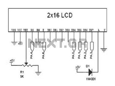
The LCD does not effectively assist in programming due to the absence of a debugging program. It is necessary to display the results of calculations, the contents of variables, or other debugging information on the LCD to understand the...
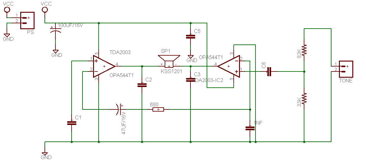
This is a design for a tone control circuit. The circuit features the LM1036, which is a DC-controlled tone (bass/treble), volume, and balance circuit suitable for stereo applications in car radios, televisions, and audio systems. The LM1036 integrated circuit is...
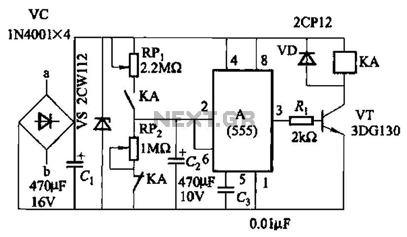
The circuit, as illustrated in Figure 3-82, employs a 555 IC to control a motor automatically, managing its start and stop cycles. The running and stopping times of the motor can be adjusted by modifying the values of potentiometers...

An embedded C-based RF-controlled robot equipped with a metal detector, along with wireless image and voice transmission capabilities. This project report is intended for electronics and communication engineering students. The project involves the design and implementation of an RF-controlled robot...

Locate sections such as the LM5020 connection diagram and pin descriptions, the functional block diagram of the device, the line under voltage lockout (UVLO) circuit, an internal high-gain error amplifier, a cycle-by-cycle overcurrent protection function, the setting of the...
This is a Voltage Controlled Oscillator (VCO) circuit. This circuit is based on a Hartley oscillator. The frequency depends on the values of C1 and L1. The Voltage Controlled Oscillator (VCO) circuit described operates using a Hartley oscillator configuration, which...