
Light alarm schematic circuit diagram

This light alarm circuit employs a Darlington phototransistor, which is sensitive to light changes, making it suitable for detecting when a drawer is opened. The core functionality relies on the interaction between the MAL12 phototransistor and the BC557 transistor, where the presence of light causes the BC557 to conduct. This action sends a high signal to the inputs of the 14011 NAND gate, initiating oscillation and triggering the alarm.
The design allows for flexibility in output configuration; the alarm can be connected to a relay for controlling higher power devices or a triac for AC applications. The choice of components reflects a balance between sensitivity and reliability, ensuring that the alarm system responds promptly to the opening of the drawer.
The delay mechanism provided by the capacitor and resistor creates a brief continuation of the alarm sound even after the light is no longer detected. This feature can be particularly useful in scenarios where immediate silence is not desired, allowing users a moment to react or address the situation. The values of the capacitor and resistor can be adjusted to modify the duration of the alarm sound, providing further customization for specific applications.
Overall, this light alarm circuit is an effective solution for alerting users to the status of a drawer or similar enclosure, enhancing security and awareness in various environments.This light alarm schematic circuit is designed using some common electronic parts, as you can see in the circuit diagram bellow. This light alarm schematic circuit project will sound as soon as the drawer is opened and light falls on the Darlington phototransistor.
The output alarm may be redesigned to activate a relay or triac. The 14011 quad, 2 input, NAND gate is wired up to oscillate when the input to it goes high, that is the BC557 transistor turns on after light is detected by the MAL12. After the alarm has started and it is put back into dark conditions, alarm will continue to sound for about 3 - 5 seconds.
This is due to the 1uF capacitor and 4M7 resistor which keep the input to the 14011 high. 🔗 External reference
Related Circuits

This circuit is capable of generating up to 1 W of audio power to drive a speaker or horn. When the CDS cell is exposed to light, its resistance decreases, activating NOR gate (a). This activation causes gates (a)...
Men often appreciate the convenience of television remote controls, which can sometimes frustrate their female partners. They tend to switch channels frequently, wanting to ensure they do not miss anything while a specific program is on. With the remote...
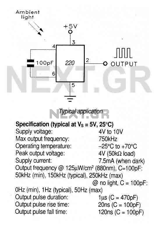
A large area photodiode and current-to-frequency converter integrated into a clear plastic 8-pin DIL package. The output generates a pulse train whose frequency is directly proportional to the light intensity. It is CMOS compatible (a 3.3kΩ pulldown resistor is...
A common issue with small flashlights is the limited lifespan of both the batteries and the bulb. For example, a typical incandescent flashlight consumes approximately 2 Watts, while the LED flashlight shown in Fig. 1 consumes only 24 mW....

Create a new project by selecting the New Project option from the Getting Started menu or by selecting File > New Project. This opens a dialog box where the desired project name and location can be entered. Choose a...
The circuit flashes an LED when detecting an incoming call and is powered by a single 1.5V cell. It is designed to detect incoming calls in a cellular phone. This circuit utilizes a simple yet effective approach to alert users...