
Digital centigrade thermometer

The circuit utilizes the ICL7106, a highly integrated analog-to-digital converter (ADC), which is specifically designed for digital voltmeter applications. The ICL7106 operates in a 3.0 to 5.0 V range and is capable of displaying readings on a 3.5-digit LCD display, making it ideal for temperature measurement applications. The silicon transistor, configured as a diode, serves as a temperature sensor, leveraging its negative temperature coefficient to produce a voltage output that varies with temperature changes.
In this design, the ICL7106 is connected directly to the LCD display, allowing for real-time temperature readings. The temperature sensing element, a diode-connected silicon transistor, provides a linear voltage output that corresponds to the changes in temperature. The negative temperature coefficient of -2 mV/°C indicates that for every degree Celsius increase in temperature, the output voltage decreases by 2 mV, necessitating careful calibration for accurate temperature readings.
Calibration involves two key steps: first, the zeroing potentiometer is adjusted while the sensor is submerged in ice water, ensuring that the output reads 0.00°C at the freezing point of water. Secondly, the scale-factor potentiometer is adjusted with the sensor placed in boiling water to ensure that the output reads 100.00°C at the boiling point. This dual-point calibration process ensures the accuracy of the thermometer across its operational range.
The circuit's simplicity and effectiveness make it suitable for various applications, including laboratory settings, environmental monitoring, and educational demonstrations. Proper implementation of this circuit can yield a reliable and accurate digital thermometer capable of precise temperature measurements.This circuit shows an ICL7106 connected with a silicon transistor to form a digital thermometer. Direct connections between the ICL7106 and an LCD display are shown in Fig. 12-11B. A diode-connected silicon transistor has a temperature coefficient of about -2 mV/ƒ. To achieve calibration, place the sensing transistor in ice water and adjust the zeroing potentiometer for a 000. 0 reading. Then, place the sensor in boiling water and adjust the scale-factor potentiometer for a 100. 0 reading. Bards Semiconductors Data Acquisition, 1991 p 2-32, 2 39 🔗 External reference
Related Circuits
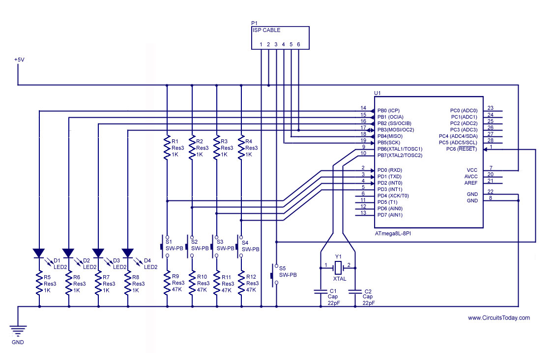
How to handle digital input/output (I/O) in AVR microcontrollers is explained using basic programs and circuits to illuminate an LED, generate a stepper motor sequence, read a push-button switch, and implement key debouncing. The handling of digital I/O in AVR...
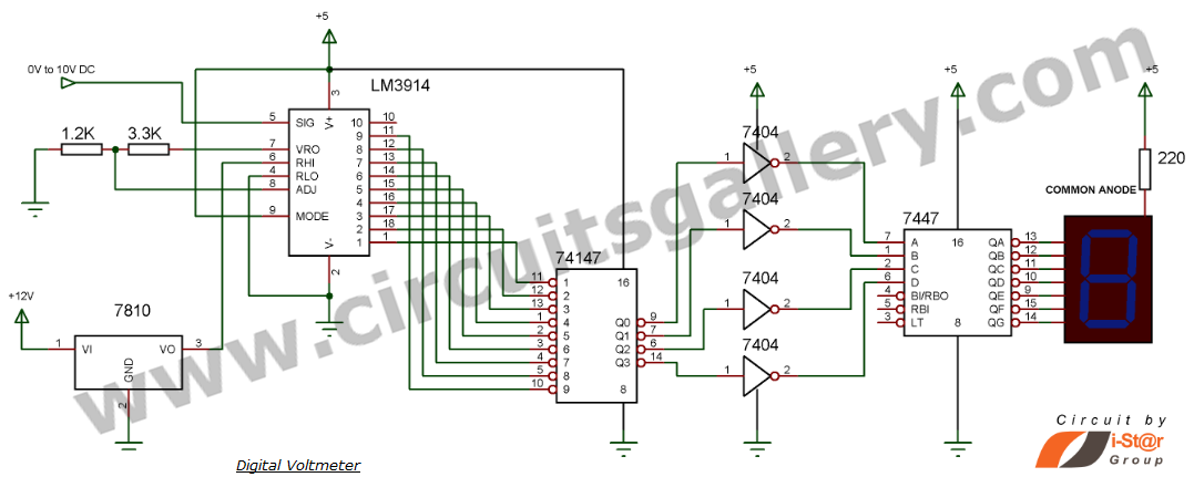
This document explains how to construct a voltmeter for measuring DC voltage without utilizing a multimeter. It describes a straightforward digital voltmeter circuit capable of measuring voltages ranging from 0V to 9V. The primary component of this circuit is...
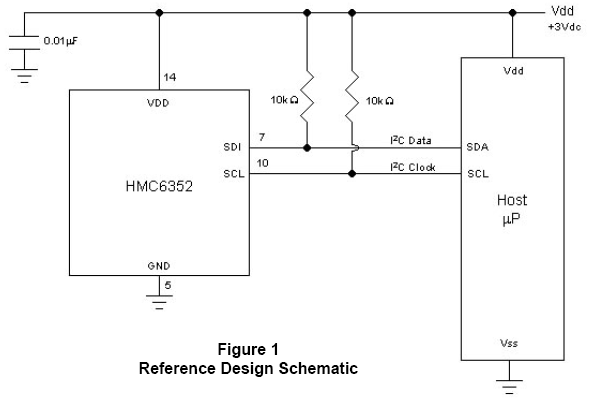
In Figure 1, the host microprocessor (uP) manages the HMC6352 through I2C serial data interface lines designated for data (SDA) and clock (SCL). Two external 10k-ohm pull-up resistors connected to a nominal 3-volt DC supply establish normally high logic...
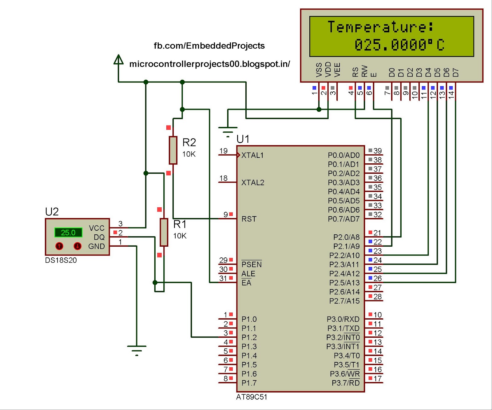
The hardware configuration for utilizing multiple 1-Wire temperature sensors, such as the DS1820, is straightforward. Communication between the microcontroller and the temperature sensors occurs over a single-wire bus, which can also supply power to the devices. An extensive number...
This circuit utilizes small switching transistors, with a maximum motor drive current limited to approximately 250 mA at 5V. Testing has been conducted across a voltage range from 3V to 21V, and with certain component modifications, it may be...
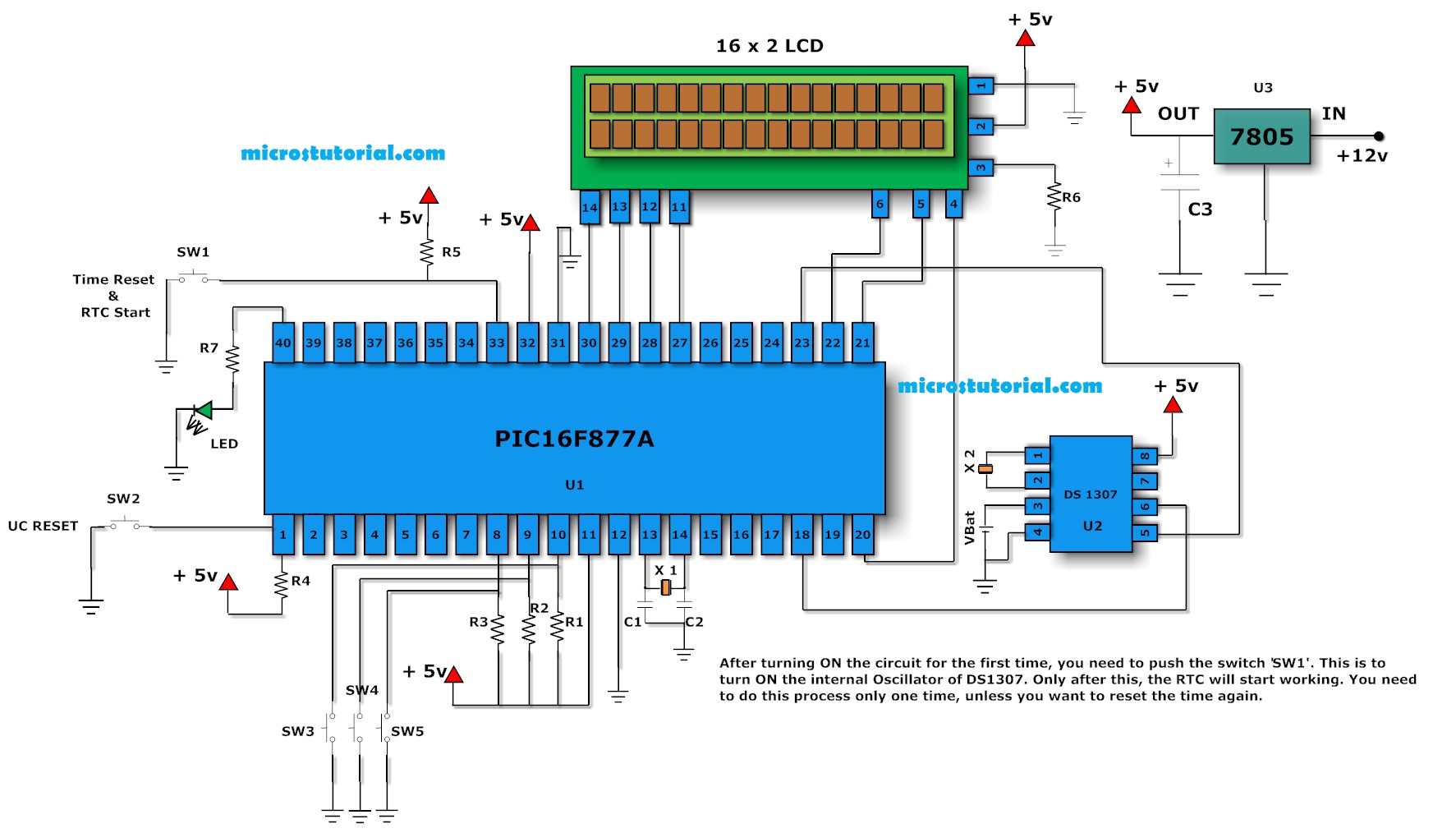
One of the main problems faced with an ordinary digital clock made using the PIC16F84 (or any other microcontrollers) is that it cannot maintain accurate time during power failures. When power fluctuations occur, the clock resets and starts counting...