
pic16f877a lcd digital clock with ds1307

The DS1307 chip is designed to provide accurate timekeeping with minimal power consumption, making it suitable for battery-operated devices. It operates on a supply voltage range of 1.0V to 5.5V, which allows it to be easily integrated into various microcontroller-based systems. The chip features a 24-hour format clock, which tracks hours, minutes, and seconds, as well as date, month, and year information, including leap year adjustments.
To interface the DS1307 with a microcontroller like the PIC16F84, a two-wire I2C communication protocol is utilized. This protocol simplifies connections, requiring only two lines: the Serial Data Line (SDA) and the Serial Clock Line (SCL). The microcontroller acts as the master device, sending commands to the DS1307, which operates as a slave device. The communication process involves sending a start condition, followed by the device address, and then the desired data or command. The DS1307 responds with an acknowledgment signal, allowing for reliable data transfer.
In addition to timekeeping, the DS1307 also provides 56 bytes of SRAM for storing user-defined data. This non-volatile memory retains information even when power is lost, making it useful for applications that require data persistence. The SRAM can be accessed similarly to the RTC registers, allowing for easy data management.
For implementation, a typical circuit would include the DS1307 connected to the PIC16F84, with appropriate pull-up resistors on the SDA and SCL lines to ensure proper signal levels. A coin cell battery is connected to the Vbat pin of the DS1307, providing backup power to maintain the timekeeping function during power outages. The microcontroller can be programmed to read the current time from the DS1307 at regular intervals and display it on a suitable output device, such as an LCD or seven-segment display.
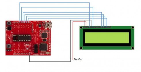
Overall, integrating the DS1307 RTC chip into a digital clock project addresses the limitations of traditional microcontroller-based timekeeping, ensuring accurate and reliable time management even in the event of power interruptions.One of the main problem facing with an ordinary digital clock made using PIC16F84(or with any other micros), where time is calculated based on the program we write in it is that, it will not be able to keep the time when power failures occur. When power fluctuations happen, it will reset and starts again. A permanent solution for this is the use of a Real Time Clock chip(RTC). These kind of chips keeps time internally in its registers and we will be able to read and display this time by reading these internal registers. The time inside RTC chips are backed up by a battery backup usually, like the one we use for BIOS back up in Computers.
The RTC we use in this project is DS1307 chip from Dallas. The DS1307 Real Time Clock is a low power, full BCD clock/calendar plus 56 bytes of nonvolatile SRAM. Address and data are transferred serially via a 2 wire bi-directional bus. 🔗 External reference
Related Circuits
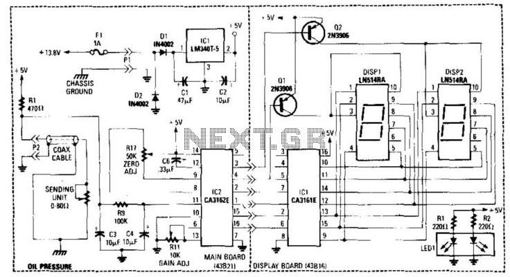
This gauge utilizes a sensor along with resistor R1 to generate a DC voltage that is proportional to oil pressure. Integrated circuits IC1 and IC2 form a two-digit digital voltmeter (DVM). Transistors Q1 and Q2 act as display selectors...
All the stages involved are designed to enable a frequency response of 20 to 100 kHz. Although such a high degree of frequency response is not necessary for this application, none of the stages have been eliminated as they...

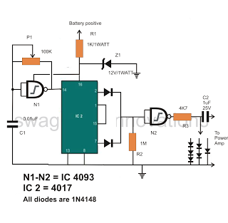
Capacitor C1 is charged through timing resistor R1 when the clock output is high. When C1 reaches the upper threshold voltage, the output signal decreases, and then C1 discharges through R1 until its voltage reaches the lower threshold point....
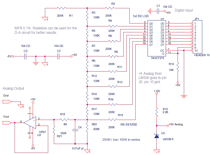
This circuit can be utilized to convert a byte sent from a microcontroller into an analog value, such as 1.51 V. At full scale, when all 8 bits are high, it is calibrated to provide 2.55 V, with each...
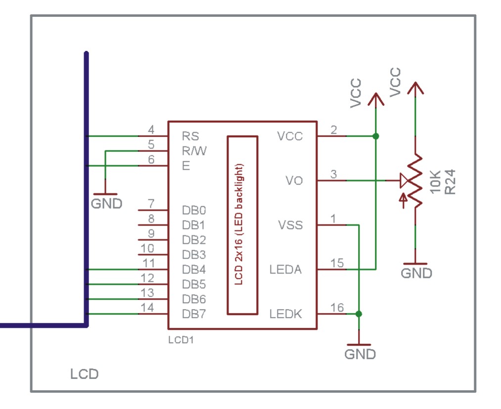
The EN line is referred to as 'Enable'. This control line is utilized to indicate to the LCD that data is being sent. To transmit data to the LCD, the program must ensure that this line is low (0),...
The Maker/hacker group Hive76, based in Philadelphia, PA, developed a compact serial terminal utilizing a TI Launchpad and an HD44780 LCD. The circuit diagram and code libraries are available for download, offering valuable resources that can be integrated into...