
Digital Entry Lock

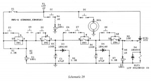
The circuit design incorporates a keypad interfaced with an LST220 integrated circuit (IC), which serves as the primary input detection mechanism. The keypad consists of a matrix arrangement that allows users to enter a four-digit code. This code is configured through the use of jumpers on a 24-pin header, enabling flexibility in code programming.
Upon entering the correct sequence, the LST220 IC processes the input and, upon validation, generates a high signal at pin 13. This output signal is crucial as it triggers the subsequent components in the circuit. Ql, typically a transistor or relay, is activated by this high signal, allowing it to switch on Kl.
Kl is responsible for driving an external electric lock solenoid, which engages or disengages the locking mechanism based on the input received from the keypad. The solenoid operates by converting electrical energy into mechanical movement, thereby securing or releasing the lock as required.
The circuit may also include additional components such as diodes for flyback protection, resistors to limit current, and capacitors for noise filtering, ensuring stable operation. The design should also account for potential security measures, such as tamper detection or feedback mechanisms, to enhance the overall security of the access control system. A keypad enters a four-digit access code, which is programmed via jumpers on a 24-pin plug-in header and socket. Ul is a n LST220, which detects a four-digit sequential data input. When the correct data is entered into the keyboard, pin 13 of Ul goes high, which activates Ql and Kl. K1 drives an external electric lock solenoid, etc.
Related Circuits
Digital IC, Electronic Lock. This is an electronic code lock that can be used as a door latch or ignition key. The operation is quite intricate, which adds to the appeal of the circuit. The electronic code lock utilizes a...
Analog peak detection is achieved by repeatedly measuring the input signal with an A/D converter and comparing the current reading with the previous reading. If the current reading is larger than the previous one, the current reading is stored...
This digital dice circuit is designed to display numbers effectively. When the spin switch is turned off, it converts the input into a binary format using a diode matrix composed of diodes D1 to D9 (1N4148 or 1N914). This...
A rectangular piece measuring 20.5 x 10.5 cm features a hole with a diameter of 1.5 cm for securing motors that facilitate the movement of the ROBO CAR using a nut and bolt assembly. The caster wheels employed in...
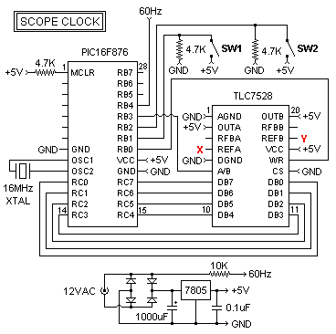
This oscilloscope clock project utilizes a PIC 16F876 microcontroller and a digital-to-analog converter (DAC) to generate X and Y signals for displaying a clock on an oscilloscope. The original circuit and software were designed by OZ2CPU. The clock circuit...
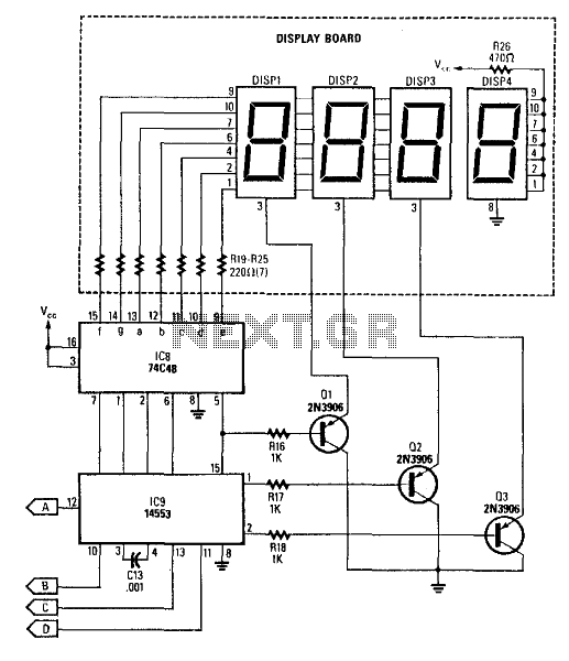
This circuit produces a readout for the digital tachometer circuit. IC9 is a 3-digit LED display driver, counter, and latch. IC8 drives the common-cathode LEDs, which are enabled by Q1, Q2, and Q3. See page 268, Fig. 46-5 for...