
Digital Clock with 6 nixies

The clock circuit design incorporates a six-digit nixie tube display, which requires a high-voltage supply of approximately 170 V for operation. Due to safety concerns, the circuit is powered by a low-voltage supply of 12 V, which is suitable for a toy application. The time-setting functionality is facilitated through a few user-friendly buttons, and the entire control logic is implemented using a microcontroller programmed in C language.
A key component of this design is the TTL IC 74141, which serves as a BCD (Binary Coded Decimal) decoder and high-voltage driver for controlling the individual digits of the nixie tubes. Given the scarcity of the 74141, alternative sourcing may be necessary, as it was a popular choice during the TTL logic era. The clock's design includes a TTL to high-voltage converter, which is essential for interfacing the low-voltage microcontroller signals with the high-voltage requirements of the nixie tubes.
For the high-voltage supply, the MC34063 step-up (boost) converter IC has been selected for its cost-effectiveness and availability. The converter circuit is adapted from the manufacturer’s datasheet, with modifications to enhance the power switch capability using an external transistor (T13) to handle the high voltage, as the internal switch of the MC34063 is not rated for such levels.
The printed circuit board (PCB) design is intended to accommodate a variety of microcontroller types, featuring a 20-pin socket that allows for easy adaptation. This universality in design facilitates the use of different microcontrollers by simply changing a few wire jumpers, thus providing flexibility for hobbyists and electronics enthusiasts.
In summary, this clock circuit is designed with safety and adaptability in mind, utilizing widely available components to create a functional and customizable nixie tube clock suitable for educational and hobbyist applications.The clock will have 6 digits and time setting will be done by means of a few buttons. I will try to use the most common types from widely used microcontroller families of miscellaneous producers. I will write the program in C language. Nixies need high voltage for operation. I wanted to avoid dangerous mains line voltage. The supply voltage for the clock must be safe 12 V. As the main target of the construction was toy, this instruction is not subtle construction with mechanical details and specified case.
You can modify the clock to your taste and qualification. Most of blocks in the block diagram are clear. Somewhat special is converter TTL/high voltage for nixies. Anode drivers are based on high voltage NPN and PNP transistors. I took the driver here. TTL IC 74141 ensures BCD decoder and high voltage driver for individual digits. Perhaps it will be difficult to come by 1 piece of it (I don't know if 74141 is produced still). But if you discovered nixies, 74141 could be near :-). In time of TTL logic fame the 74141 was almost exclusive alternative. So try to find one. Nixie need voltage about 170 V. It would be useless to design special circuit for voltage converter. There is a lot of IC for step-up (boost) converters. I selected low cost and widely available MC34063. The converter circuit is almost copied from data sheet. Just only power switch is strengthened by T13. Internal switch is not suitable for such high voltage. All microcontroller manufacturers design specific families and types. Pin configurations of individual types are various. I tried to design universal PCB for several microcontrollers. There is 20 pin socket on the board. You can adapt it for miscellaneous microcontrollers with a change a few wire jumpers. Types tested by me are listed below. You can try additional types. Processor option is advantageous. Amateur of electronics applies one microcontroller family usually and his hobby corner is equipped with programmer and tools for this family. It can be problem to use microcontrollers from other manufacturers. You can choose your favourite processor below. Ready for use is type, source and binary code, development tools and programmer. 🔗 External reference
Related Circuits
This project is a GPS-based clock that displays the current date, automatically adjusts for daylight saving time, shows current speed, maximum speed, and present heading in degrees relative to true north. The original firmware and concept were developed by...
The WWVB signal is broadcast as a 60 kHz carrier that is AM modulated with a time code frame that is updated once per minute. The data rate is one bit per second. Along with time code information, the...
A digital storage oscilloscope (DSO) is a very important piece of test equipment that can do the jobs that a normal CRO just can't handle. Such as capturing single shot and widely spaced waveshapes, and looking at non-repetitive signals...
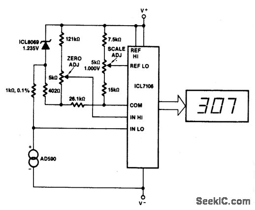
This circuit allows for zero adjustment as well as slope adjustment. The ICL8069 brings the input within the common-mode range, while the 5 K pots trim any offset at 218 °K (-55 °F) and set the scale factor. The...
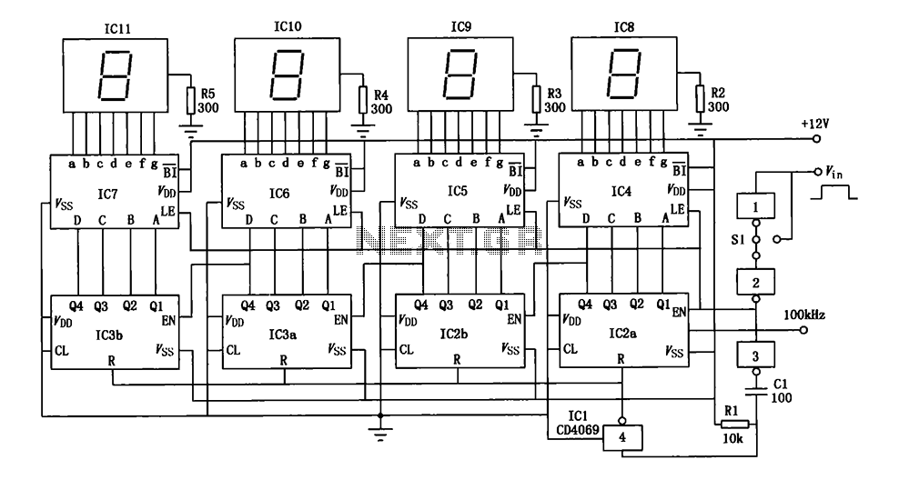
A digital pulse width measurement circuit is presented. It operates with a 100 kHz reference frequency to count the pulse width of the input signal. The count value represents the measured pulse width displayed on four seven-segment LED displays....
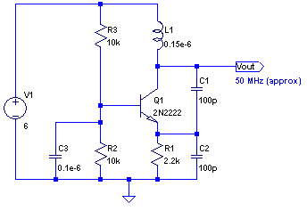
The core of any transmitter is typically an oscillator circuit, and in simple transmitters, such as QRSS devices, a crystal is often used. Frequency adjustment is achieved by modifying the capacitance to ground on one of the crystal's legs....