
Digital pulse width measurement circuit diagram CD4518 and CD4069 the

The digital pulse width measurement circuit is designed to accurately determine the duration of input signal pulses. The circuit's operation begins with a 100 kHz clock signal that provides a stable timing reference. This clock signal is fed into the CD4518 dual BCD adder counter (IC2 and IC3), which counts the number of clock pulses corresponding to the width of the incoming pulse.
The resolution of the measurement is set at 10 microseconds, allowing for precise readings of pulse widths. The maximum pulse width that can be accurately measured is 99.99 milliseconds. When a pulse is detected, the counters increment based on the duration of the pulse, effectively translating the pulse width into a count value.
To display the measured pulse width, the circuit employs four seven-segment LED displays. The output from the CD4518 is fed into the CD4511 BCD latch/decoder/drivers (IC4 to IC7). These components convert the binary-coded decimal (BCD) output from the counter into a format suitable for driving the seven-segment displays, allowing for a clear visual representation of the measured pulse width.
In summary, this digital pulse width measurement circuit effectively combines precise counting and visual display components to measure and present pulse widths in a user-friendly manner. The integration of the CD4518 and CD4511 ICs ensures accurate counting and display, making it suitable for various applications in electronics where pulse width measurement is required.Digital pulse width measurement circuit is shown. It uses a l00kHz reference frequency, the count in the pulse width of the signal, the count value of the product of the resolu tion on behalf of the measured value of the pulse width by four seven-segment LED display. Resolution circuit is 10 s, the maximum width is measured 99.99ms. IC2, IC3 dual BCD adder counter CD4518; IC4 ~ IC7 to BCD seven latch/decoder/driver CD4511.
Related Circuits
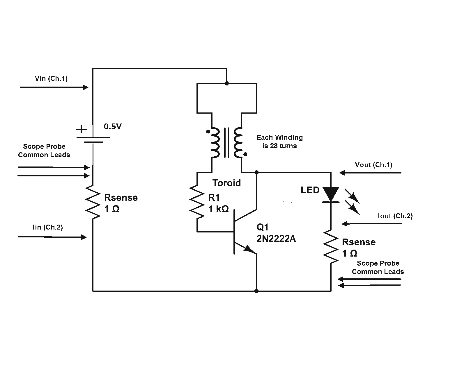
Is a Joule Thief circuit capable of achieving overunity? Joule Thief schematic including scope measurement points. The Joule Thief is a minimalist circuit designed to extract energy from low-voltage sources, such as depleted batteries, and convert it into a usable...
VOX is a voice-controlled switch commonly used for microphones, serving as a replacement for the traditional switching button. The actuating threshold is adjusted through the volume potentiometer. The VOX (Voice Operated Switch) circuit functions by detecting sound levels and activating...
An LED, or Light Emitting Diode, is a semiconductor device that allows current to flow in one direction while blocking it in the opposite direction. This characteristic makes LEDs polarized components, having a positive side known as the anode...
This circuit generates dual-tone bell sounds similar to those found in standard doorbell units. It is applicable in various contexts beyond doorbells. The circuit, as depicted in the diagram, produces a "Ding-tone" when switch P1 is pressed and a...
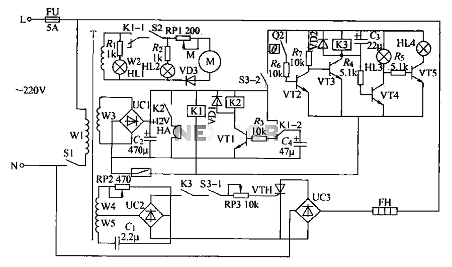
A chemical mixer circuit equipped with stirring speed control, a thermostat, and a timer alarm function is suitable for use in the chemical, steel, and other industries. The circuit includes components for heating, magnetic stirring, motor control, and timing...
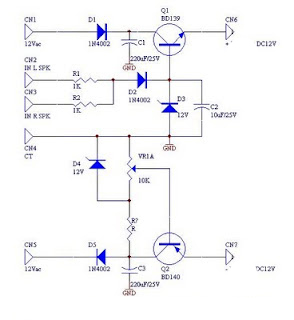
DC fan control circuit for a power amplifier. It features a variable speed DC fan that operates based on the input signal. The speed of the fan's rotation is dependent on the amplitude of the input signal received from...