
gps driven clock compasss peedo

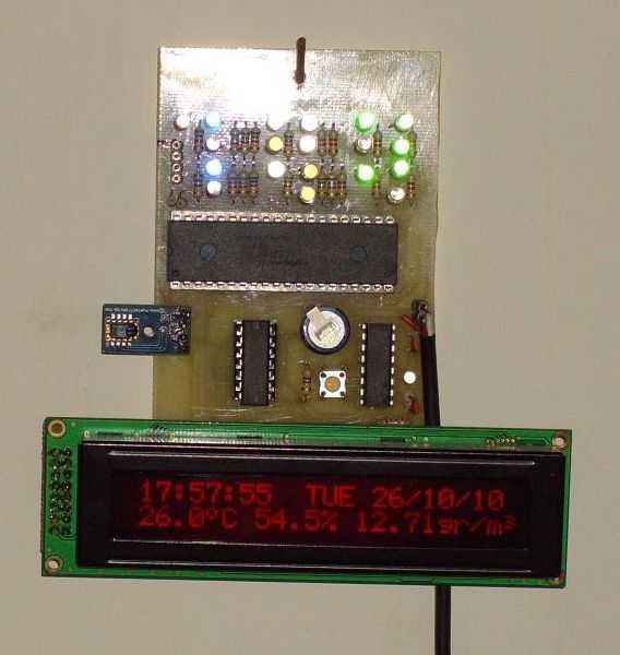
The GPS-based clock circuit consists of several key components, including a microcontroller, a 16x4 LCD display, and the EM 406A GPS engine. The microcontroller serves as the central processing unit, managing data from the GPS module and controlling the display output. The EM 406A GPS engine receives satellite signals and provides NMEA sentences, which contain crucial data such as time, date, speed, and heading.
The 16x4 LCD display is utilized to present this information clearly to the user. The microcontroller is programmed to parse the incoming NMEA sentences, extracting relevant data while ignoring unnecessary sentences that may cause conflicts, such as the $GPVTG, which was problematic in earlier firmware versions.
To achieve accurate timekeeping and date display, the microcontroller is programmed to automatically adjust for daylight saving time based on the geographical location obtained from the GPS. The speed measurements are calculated from the GPS data, with the maximum speed feature implemented through a simple comparison algorithm that retains the highest speed recorded during operation. This function is particularly valuable for users who wish to monitor the performance of their vehicles over time.
The overall design emphasizes reliability and accuracy, ensuring that the device can operate effectively across various environments and applications. By leveraging the capabilities of the EM 406A GPS engine and the flexibility of the microcontroller, this project exemplifies a practical integration of GPS technology into everyday devices, enhancing the user experience through real-time data display and logging functionalities.This project is a GPS based clock, which also displays the present date, automatically compensates for daylight savings time, displays current speed, and maximum speed, along with your present heading in degrees with respect to true north. The original firmware and concept came from Ken, VK7KRJ, who was kind enough to grant me permission to use hi
s source code and his original circuit idea in this project. I have modified the source code to work with the 16x4 display module that I have used, as well as the EM 406A GPS engine that I have built into the box. I have discovered that from one GPS engine to another, the NMEA sentences can vary slightly, depending on which chipset is used in the GPS engine.
The EM 406A is a SiRf III based GPS, and Kens source code was written in 2004, so it is compatible with older GPS`s, but required modification to work with my SiRf III GPS. I basically had to stop the code from loading the $GPVTG sentences from the GPS module, as this is where the original firmware got stuck.
I also added the code for the unit to log the maximum speed achieved, and keep it on the display indefinately, which makes this unit useful for logging the maximum speed achieved by a model car, or a dirt bike, or any other vehicle not already equipped with a speedo. 🔗 External reference
Related Circuits
In the circuit below, 60 individual LEDs indicate the minutes of a clock, while 12 LEDs represent the hours. The power supply and timing circuitry are similar to those described in the previous 28 LED clock circuit. The minute...
The current source in the diagram reacts very quickly to changes in the input signal and may be utilized in specific measurements. Differential. The current source depicted in the schematic is designed to provide a stable output current that responds...
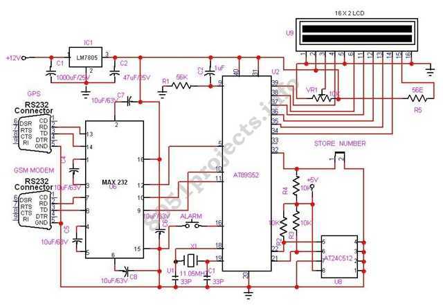
In this project AT89S52 microcontroller is used for interfacing to various hardware peripherals. The current design is an embedded application, which will continuously monitor a moving Vehicle and report the status of the Vehicle on demand. For doing so...
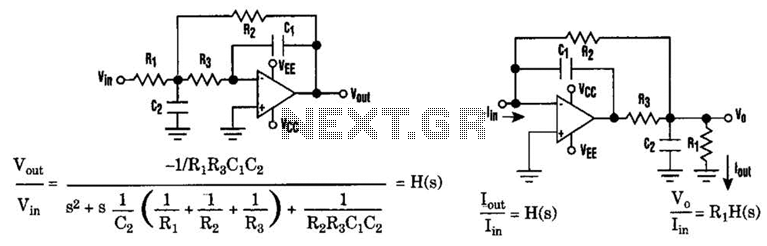
The low-pass Sallen-Key filter is a staple for designers because it contains few components. By redesigning the filter, a current-to-voltage conversion can be avoided when the input signal to be filtered is in current form. The Sallen-Key filter is a...
I use a RealTimeClock Maxim DS1305. The RTC backup power is a supercapacitor (0.22F). I test it for 4 weeks, works fine. For this reason it doesn't have the capability to change the time, but you can do small...
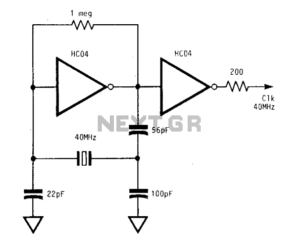
The circuit operates reliably from below 1 MHz to above 400 MHz. With a supply voltage (Vcc) of 5 V, the output of the second inverter achieves a full swing from 0 V to 5 V. These significant logic...