
Digital Counter - 4029 and 4511

The IC 4029N is a binary up/down counter that can count in both directions, while the 4511N is a BCD (Binary-Coded Decimal) to 7-segment latch/decoder/driver. The 4029N features a maximum count of 15 (in binary) and can be configured to count up or down based on the input control signals. It includes features such as asynchronous reset, parallel load capability, and an enable input for counting operations.
The 4511N, on the other hand, takes a 4-bit BCD input and drives a 7-segment display, translating the binary-coded value into a human-readable format. It includes latching capabilities, allowing the output to maintain its state until explicitly changed, which can be useful in applications where the display should not change until a new input is provided.
In a circuit design utilizing both ICs, the 4029N could be employed to count events or time intervals, while the 4511N would convert the count into a visual representation on a 7-segment display. Proper interfacing between the output of the 4029N and the input of the 4511N is essential to ensure accurate representation of the counter's state on the display. Additional components, such as resistors for current limiting and capacitors for debouncing, may also be required to enhance the circuit's performance and reliability.
Overall, the combination of these two ICs allows for effective counting and display of numerical values in various electronic applications, such as timers, event counters, and scoreboards.I just about the circuit you made. what kind of IC is 4029N & 4511N Is it a diver/decoder I tried to research on the datasheet but it cannot give exact specification. 🔗 External reference
Related Circuits
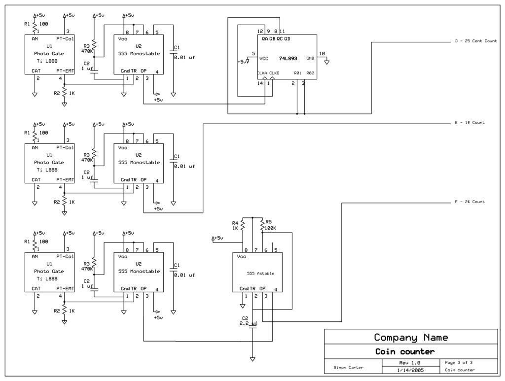
The next counter section operates similarly but is designed to count four quarters, single $1 coins (loonies), and single $2 coins (toonies). The circuit for the toonies is configured. The circuit for the counter section includes a digital counting mechanism...
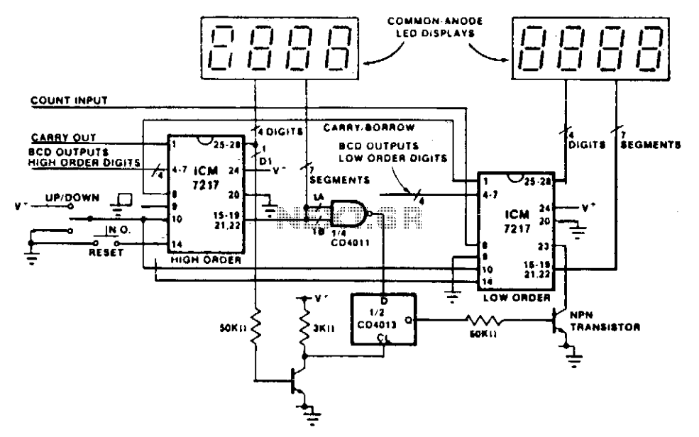
This circuit illustrates the method of cascading counters while maintaining the appropriate leading zero blanking. A NAND gate is employed to determine if a digit is active, as indicated by the activation of either segment a or b on...
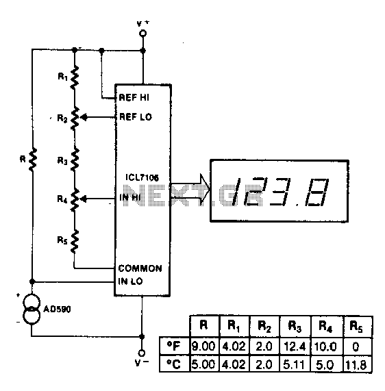
The maximum reading on the Celsius range is 199.9 °C, which is limited by the short-term maximum allowable sensor temperature. The maximum reading on the Fahrenheit range is 199 °F (93 °C), constrained by the number of display digits....
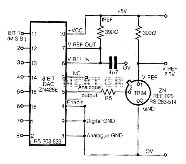
This circuit demonstrates a straightforward approach to achieving a voltage reference that can be adjusted using an 8-bit Digital-to-Analog Converter (DAC) equipped with an integrated voltage reference. The analog output from the DAC controls the trim pin of the...
The AT89C2051 Digital Visitor Counter utilizes a microcontroller to perform its function by receiving signals from sensors. The AT89C2051 Digital Visitor Counter is designed to accurately count the number of visitors entering or exiting a designated area. This system employs...
This design synthesis considers the accuracy of frequency measurement and the requirements for response time. For instance, when measuring a frequency of 1 Hz, the measurement duration must exceed 1,000 seconds to accurately count the gate width. To ensure...