
Digital display pressure measuring circuit diagram

This digital display pressure measuring circuit is designed to accurately measure and display pressure values through a digital interface. The circuit utilizes an analog-to-digital converter (ADC) to translate the analog input signal, which represents pressure, into a digital format that can be displayed on a digital readout.
The power supply for this circuit is specified at 12.8V, which is essential for the operation of the ADC and other electronic components. The current consumption of 30mA indicates a low-power design, suitable for battery-operated or energy-efficient applications.
The input voltage range of 0.8mV signifies that the circuit is capable of detecting very low pressure changes, making it suitable for high-precision applications. The maximum gain setting enhances the sensitivity of the circuit, allowing it to respond to minute variations in pressure.
The zero adjustment range of ±1mV/V provides flexibility in calibrating the circuit to account for any offsets that may occur during operation, ensuring that the displayed values are accurate. The display can show values from 0 to 1999, accommodating a wide range of pressure measurements.
Additionally, the zero shift specification of 2µV/°C indicates the temperature stability of the circuit, which is critical in applications where temperature variations can affect pressure readings. The additional voltage shift of 0.005% ensures that the circuit maintains its accuracy over time, further enhancing the reliability of the measurements.
This circuit can be integrated into various applications, including industrial pressure monitoring systems, laboratory equipment, and portable pressure measurement devices, where precision and reliability are paramount. Proper implementation of this circuit will require careful consideration of component selection, layout design, and calibration procedures to achieve optimal performance.The figure is a digital display pressure measuring circuit diagram. The performance of this circuit: the additional voltage is about 12.8V, the current is 30mA; when it is maximum gain, the input voltage range is 0.8mVW; the zero adjustment range is ±1mV/V; the shown value is 0-1999; the zero shift is 2?V/?; the additional voltage shift is 0.005%?; the.. 🔗 External reference
Related Circuits
A modulated current is supplied by the integrated rotational speed sensor KMI 15/x. This current signal needs to be converted into a ground-referenced voltage signal. The KMI 15/x sensor operates by generating a modulated current proportional to the rotational speed of...
Involvement is a modified version of the classic circuit of automatic level control signal used in tape recorders. The purchase price of the components (using TL072) does not exceed CZK 60 for a channel. For a range of entry...
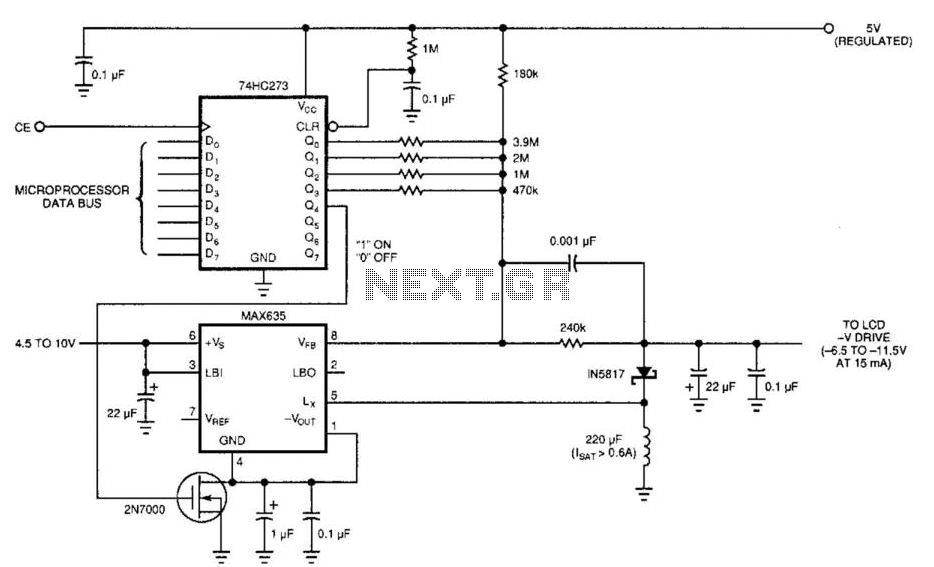
Laptop computers frequently utilize large-screen LCDs that require both a variable and a negative supply to achieve maximum contrast. This circuit operates from the system's positive battery supply and generates a digitally variable negative voltage to drive the display....
Circuit diagram schematics of electronic keys, electronic locks, digital electronic locks, transistor code locks, and combination electronic locks. The circuit schematics for electronic locking mechanisms encompass a variety of designs tailored to enhance security and convenience in access control systems....
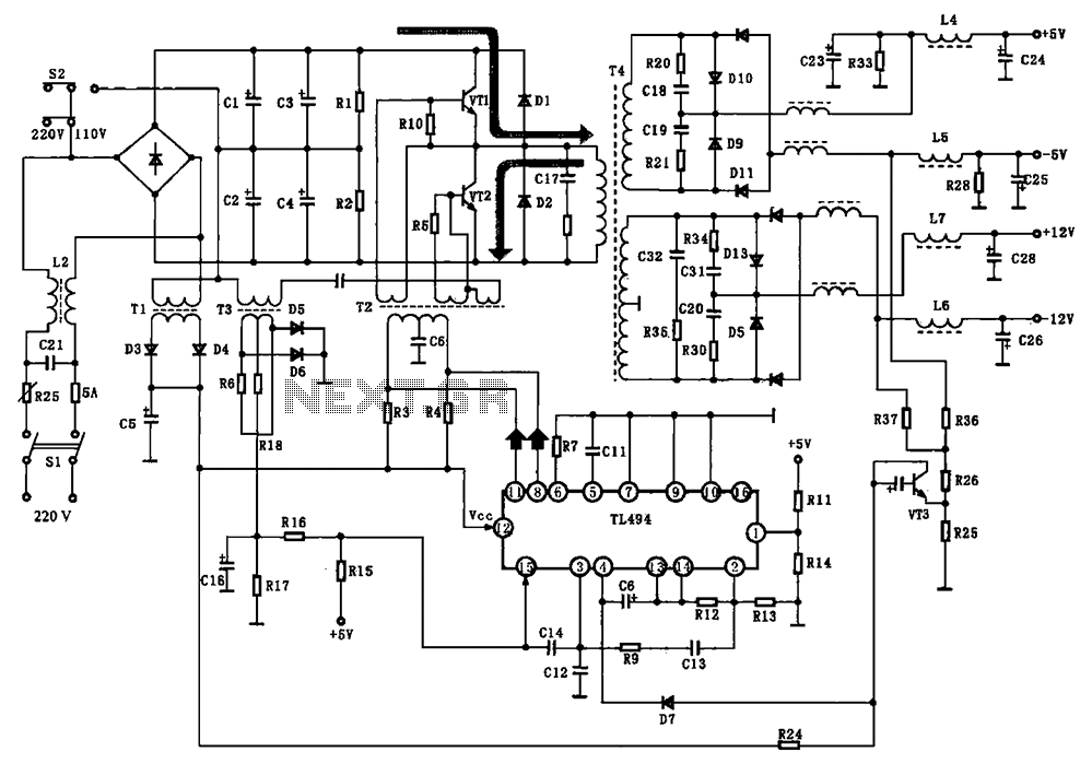
The BE-150 mainframe computer features a switching power supply circuit. The circuit utilizes the oscillation control IC TIA94. A 22V voltage is supplied through the power switch S1, fuse, filter capacitor C21, L2, and a mutual inductance filter, which...
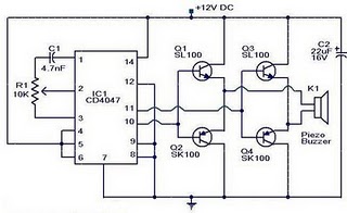
The circuit operates on the principle that insects, such as mosquitoes, can be repelled using sound frequencies in the ultrasonic range (above 20 kHz). It utilizes a Phase-Locked Loop (PLL) integrated circuit, specifically the CMOS 4047, configured as an...