
Signal Conditioning Circuit for KMI 15/x Rotation Speed Sensor

The KMI 15/x sensor operates by generating a modulated current proportional to the rotational speed of an object. To utilize this current signal in most electronic circuits, it is necessary to convert it into a voltage signal that is referenced to ground, as this is the standard for most analog input stages.
The conversion can be achieved using a resistor or a current-to-voltage converter, commonly known as a transimpedance amplifier. In the simplest form, a resistor can be placed in parallel with the output of the sensor. The resistance value should be chosen based on the expected range of the modulated current, ensuring that the resulting voltage falls within the input range of the subsequent processing circuitry.
For a more precise and linear conversion, a transimpedance amplifier is recommended. This configuration typically involves an operational amplifier (op-amp) where the output voltage is directly proportional to the input current. The feedback resistor in this setup determines the gain of the circuit, allowing for flexibility in scaling the output voltage to match the required specifications of the connected devices.
It is also essential to consider the bandwidth and response time of the circuit, as the dynamics of the rotational speed may require fast response times. Proper filtering techniques may be employed to reduce noise and improve signal integrity. Additionally, protection mechanisms such as clamping diodes may be incorporated to safeguard the circuit from potential overvoltage conditions.
Overall, converting the modulated current from the KMI 15/x sensor into a ground-referenced voltage signal is a critical step for interfacing with other electronic components, ensuring accurate readings and reliable performance in various applications.A modulated current is provided by the integrated rotational speed sensor KMI 15/x. This current signal must be converted to ground referenced voltage signal,. 🔗 External reference
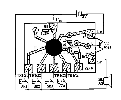
Related Circuits
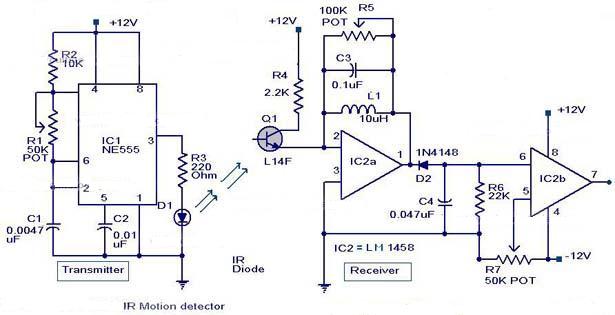
The following circuit illustrates an Infrared Motion Sensor circuit diagram. Features include the use of the NE555 integrated circuit, with a detection zone coverage of 80 degrees. The Infrared Motion Sensor circuit utilizes the NE555 timer IC configured in a...
The T-40-16 and 555 ultrasonic transmitter circuit configuration consists of an ultrasonic transmitter T-40-16 and a 555 timer circuit. By adjusting the potentiometer RP, the oscillation frequency of the circuit can be changed. The output pulse frequency from the...
Electronic temperature control circuit for imported car air conditioners. It utilizes operational amplifiers A1 and A2, specifically the LM393 model. An adjustment potentiometer (RP) is included, allowing modification of the temperature range. The adjustment range includes a power temperature...
This schematic represents a cable TV signal booster amplifier circuit designed to enhance the signal strength of a cable TV system. It is recommended to use 75 Ohm coaxial cables for both the input and output connections, and the...
Constantly changing light and sound analog controller circuit 07 The circuit described is an analog controller designed to modulate light and sound in a dynamic manner. This circuit utilizes various electronic components to create an interactive experience where both light...
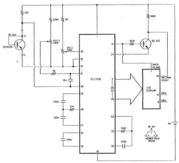
The ICL7106 integrated circuit contains all the active circuitry for a 3 1/2 digit panel meter (DPM) in a single chip. It was designed to interface directly with a liquid crystal display (LCD). The potential difference across a silicon...