
Digital Encoder with PIC16F57

This circuit is designed to encode and transmit the state of up to 16 TTL (Transistor-Transistor Logic) digital inputs, utilizing either RF (Radio Frequency) or infrared (IR) transmission methods. The core of the system is a PIC microcontroller, which provides significant flexibility in configuring the inputs and outputs for various applications.
Upon activation, the integrated modulator generates a 38kHz carrier signal for IR transmission, allowing the system to communicate effectively over short distances. The circuit's design enables the user to specify which of the 16 digital inputs will initiate a transmission, providing tailored control based on the specific needs of the application.
The output from the transmitter employs Manchester encoding, a method that is particularly compatible with low-cost ASK (Amplitude Shift Keying) radio modules and is suitable for infrared control systems. This encoding technique enhances the reliability of data transmission by ensuring that the signal is self-clocking, which is beneficial in noisy environments.
The circuit also includes a LATCH input, which allows the user to configure the behavior of the receiver outputs. This input can be set to control whether the outputs are latched (maintained) or momentary (activated only during the transmission), thus accommodating a range of operational requirements.
It is important to note that the circuit does not currently support address decoding, which may limit its application in more complex systems requiring unique address identification for multiple transmitters.
For those who encounter difficulties in programming the PIC microcontroller, alternative circuits based on Holtek HT-12D, HT-12E, or Motorola MC145026, MC145027, MC145028 encoders and decoders are recommended. These alternatives may provide simpler solutions for users less familiar with PIC programming.
The microcontrollers utilized in this design are FLASH-based, allowing for multiple reprogramming cycles. This feature enables users to modify and experiment with the source code to better suit their specific needs. The programming must be conducted as a linked project using the MPLAB integrated development environment, and users are encouraged to refer to the FAQ section on the PIC page for additional guidance and troubleshooting assistance.This encoder can transmit the state of up to 16 TTL digital inputs using an RF or infrared transmitter. When enabled, the included modulator automatically generates the 38kHz IR carrier. Containing a PIC microcontroller, the circuit is very flexible. You can decide which transmitter inputs will trigger a transmission. You can control the receiver outputs to be latched or momentary with the LATCH input. The Manchester-coded transmitter output is well suited for the cheapest ASK radio modules or for infrared control.
Address decoding is not yet supported. If you have trouble with programming PIC microcontrollers, you can consider builing other circuits based on Holtek HT-12D, HT-12E and Motorola MC145026, MC145027, MC145028 encoders/decoders. All the devices use new, FLASH-based microcontrollers, this means that they can be re-programmed many times. You can experiment with the source code settings to fit your needs. The code must be compiled as a linked project under MPLAB. Please check FAQ at the PIC page. 🔗 External reference
Related Circuits
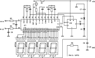
This circuit is a digital voltmeter with an LED display, ideal for measuring the output voltage of a DC power supply. It features a 3.5-digit LED display with a negative voltage indicator and measures DC voltages from 0 to...
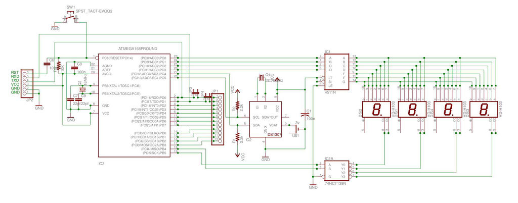
This is the second instructable focused on creating a digital watch as a learning experience. An Atmega644 chip from a Sanguino was available, which would have sufficed, but the intention was to burn an Arduino bootloader and test its...
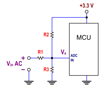
The ATtiny24 microcontroller's ADC is utilized to record an AC signal, which operates within a voltage range of 0 to 3.3V. A precision rectifier is employed to eliminate the negative portion of the signal. The circuit incorporates an LMC6484...
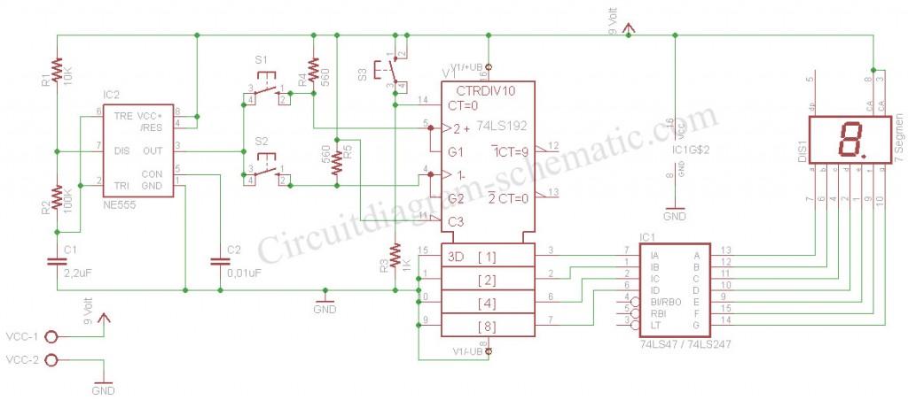
The digital scoreboard circuit is designed to display numerical values ranging from 0 to 9 on a 7-segment display. This display utilizes a common anode configuration. The digital scoreboard circuit operates by controlling a 7-segment display that utilizes a common...

This circuit is based on the UM5100, which can record speech into digital memory and then play it back. The device is designed for use with static RAMs up to 256K bits or with EPROMs or ROMs for playback...
The motor is utilized to provide the mechanical output of the system and to move the potentiometer for loop closure. For high-power servos, three-phase motors can be employed. Potentiometer: A simple potentiometer can be used for standard industrial applications...