
Digital Tachometer Counter

The described circuit is designed to provide a visual display of rotational speed in a digital tachometer application. The core component, IC9, serves as a multifunctional device that integrates a 3-digit LED display driver, a counter, and a latch. This allows for the accurate counting of input pulses generated by a sensor that detects the rotation of a shaft, converting these pulses into a readable digital format.
IC8 is responsible for driving the common-cathode LEDs, which illuminate the display. The common-cathode configuration indicates that each LED's cathode is connected to ground, while the anodes are driven high by IC8 to turn on the respective segments of the display. The enabling transistors, Q1, Q2, and Q3, act as switches to control the power to the LED segments, ensuring that only the relevant segments are illuminated based on the counter's output.
In conjunction with these components, the circuit may include additional elements such as resistors to limit current through the LEDs, capacitors for filtering, and potentially diodes for reverse voltage protection. The design also incorporates feedback mechanisms to ensure stable operation and accurate readouts. The reference to page 268, Fig. 46-5 suggests that there is a related project or schematic that may provide further insights into the implementation and functionality of this tachometer circuit. This circuit produces a readout for the digital tachometer circuit. IC9 is a 3-digit LED display driver, counter , and latch. IC8 drives the common-cathode LEDs, which are enabled by Ql, Q2, and Q3. See page 268, Fig. 46-5 for the matching project.
Related Circuits
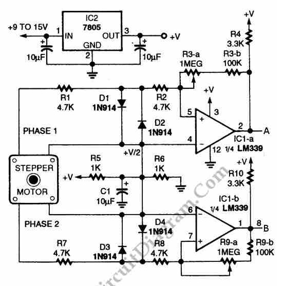
The circuit illustrated in the schematic diagram below allows for the visualization of the direction and shaft rotation of a stepper motor on an LED display. Instead of utilizing a digital rotation encoder as an input, this circuit employs...
The attached schematic diagram is a Johnson Counter. Please provide advice on why "Loop 2" is considered to be invalid. Additionally, please suggest a few alternatives. The Johnson Counter, also known as a twisted ring counter, is a type of...
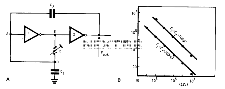
This simple, low-cost oscillator is constructed using two CMOS buffer inverters, two capacitors, and a variable resistor. The circuit operates with voltage levels ranging from 4 V to 18 V. When C1 equals C2, the frequency of oscillation is...
The objective of this project is to create a controller-based model that counts the number of individuals entering a specific room and activates the lighting accordingly. This is achieved through the use of sensors that detect the current number...

The circuit for the Digital Tachometer/RPM Counter consists of a few components. They should be connected according to the provided circuit diagram. The PIC used is on a demonstration board, meaning the clock, power, and ground pins are already...
This digital volume control has no pot to wear out and introduces almost no noise in the circuit. Instead, the volume is controlled by pressing UP and DOWN buttons. This simple circuit would be a great touch to any...