
Digital Dice circuit

The digital dice circuit operates by employing a diode matrix that facilitates the conversion of the switch states into a binary representation. Each diode in the matrix, designated as D1 through D9, plays a crucial role in determining the output based on the combination of active switches. The choice of diodes, such as the 1N4148 or 1N914, ensures reliable switching characteristics and minimal forward voltage drop, which is essential for accurate binary conversion.
When the spin switch is deactivated, the circuit interprets the closed or open states of the switches as binary inputs. These binary inputs are fed into the CD4511 decoder driver IC, which is responsible for translating the binary values into corresponding outputs suitable for driving a 7-segment display. The CD4511 is a BCD to 7-segment latch decoder that can effectively handle the binary-coded decimal values, allowing for seamless conversion and display of numbers ranging from 0 to 9.
The 7-segment display is connected to the outputs of the CD4511, which activates the appropriate segments to visually represent the corresponding decimal number. This setup ensures that the circuit can reliably display the results of the dice roll, providing a clear and user-friendly interface. The overall design of the circuit emphasizes simplicity and efficiency, making it an ideal choice for applications requiring a digital representation of random numbers.This dice digital circuit would be a favorite of everyone, by using it to display the numbers. When I turn off the spin switch, it will be converted to a binary input with a diode matrix D1-D9 (1N4148 or number 1N914) and then changed to a 7 segment display with a decoder drive IC No. CD4511 (IC3). 🔗 External reference
Related Circuits
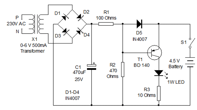
Circuit diagram for a mini emergency lamp. This mini emergency lamp activates during power failures to provide cool white light in the room. It utilizes a 1-watt white LED to deliver adequate illumination. The circuit for the mini emergency lamp...

Pressing the START pushbutton activates either the headlights or spotlights for a specified duration. After 1 minute, determined by R1 and C1, the lights will turn off as the NE555 timer completes its cycle. The circuit utilizes a NE555 timer...
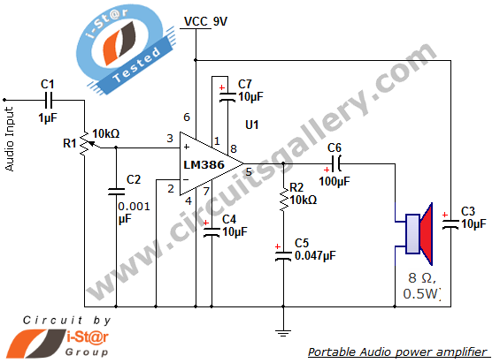
The i-St@r presents a simple mini audio amplifier circuit schematic utilizing the LM386 low voltage audio power amplifier IC. This circuit is designed to power medium-sized speakers from a music player that typically drives only earphones (LM386 headphone). The...
Humidity detector circuit electronic project using common electronic parts The humidity detector circuit is a project designed to measure and indicate the level of humidity in the environment. This circuit utilizes commonly available electronic components, making it accessible for hobbyists...
WinCircuit is a software of realization of drawing of printed circuit in single or double layers. Principal qualities are the facility of use and the sight in pseudo 3D which gets a vision of the circuit close to reality....
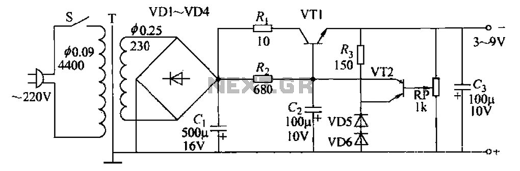
A 3-9V adjustable 100mA power supply is presented, featuring a series regulator circuit that utilizes amplifier tubes. The output voltage can be continuously adjusted between 3V and 9V, with a maximum output current of 100mA, making it suitable for...