
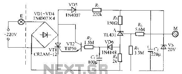
Single-ended forward converter circuit

At 0% RH, the humidity capacitance (C) is not zero, necessitating compensation through the switched capacitors at pins 7, 8, 12, 13, 11, and 14. As A2 inverts the signal, a positive voltage is applied to the inverting input of A3, where A2 connects to the inverting input of the switched capacitor resistors for temperature compensation. Capacitors C6 (330 pF), C4 (470 pF), and C5 (0.01 µF) are selected to have the same temperature coefficient, ensuring they remain unaffected by temperature changes, similar to the humidity capacitance (C).
The voltage at A3's inverting input remains constant. If the stepped waveform output voltage from A1 is lower than this inverting input voltage, A3's output is low; if higher, the output is high. The discharge through VT and C5 is inversely proportional to the timing of each step from the initial state to the increased size of the stepped waveform from C5. This process corresponds to a clock pulse period that is proportional to the charge accumulated in the humidity capacitor (C), which is inversely proportional to the capacitance.
The process is repeated until the stepped waveform output voltage from A1 equals the inverting input voltage of A3, resulting in an output pulse from A3. The pulse duration is inversely proportional to the humidity capacitance, which in turn affects the frequency and capacity. The first adjustment of RP1 (10 kΩ) sets the output signal frequency to 50 Hz at 5% RH, followed by the adjustment of potentiometer RP2 (20 kΩ) to achieve a frequency of 900 Hz at 90% RH. Once calibrated, the circuit provides an output signal frequency ranging from 0 to 1000 Hz for humidity levels of 0 to 100% RH, with an accuracy of 2%.
The schematic of the humidity/frequency conversion circuit illustrates the integration of various components, including the LTC1043, capacitors, and resistors, to achieve precise humidity measurement and conversion into frequency signals. The design emphasizes stability and accuracy across a wide range of humidity levels, making it suitable for applications requiring reliable humidity monitoring.FIG humidity / frequency conversion circuit. The same as the above humidity sensors, humidity 76% isochronous The equivalent capacitance of 500pF, capacitive relative humidity variation rate was +1.7 pF /%. Circuits, A1 is the integrating circuit, which is proportional to the integral current humidity. A reference voltage generating circuit A2, A3 is a comparison circuit. When the LTC1043 16 feet off, the internal clock circuit, the operating frequency of about 150 kHz. 2 feet and 6 feet short, humidity capacitance C with a negative voltage charge. When 2 feet and 5 feet short, the current flowing into the inverting input of A1, the output voltage rises. Repeat the above process, A1 output is stepped wave voltage. In fact, when the humidity is 0% RH, humidity capacitance capacitor C is not zero, so to compensate, and 7,8 and 12, 13 and 11 feet and 14 feet of the switched capacitor is set for this.
Since the effect of A2 is inverted, a positive voltage is applied to the inverting input terminal of the A3, A2 corresponds to the inverting input of the switched capacitor resistors, for temperature compensation. As the capacitor C6 (330pF), the capacitor C4 (470 pF), and a capacitor C5 (0.01 F) is the same as the temperature coefficient, hence, are not affected by temperature changes.
In addition, humidity capacitance C capacity is not affected by temperature changes. Since A3 inverting input voltage constant, if the step wave output voltage A1 is less than the inverting input voltage, A3 output is low; if higher than the inverting input voltage, the output is high A3, VT guide pass, C5 through VT discharge, discharge voltage is inversely proportional to each step of the ending time from the start state to C5 stepped wave of increased size. This is equivalent to a clock pulse period proportional to the charge accumulated in the capacitor C in humidity, that is inversely proportional to the capacitance.
Repeat the above process, step wave output voltage A1 inverting input voltage equal to A3, A3 output pulse. Pulse duration is inversely proportional to the capacitance humidity, which is inversely proportional to frequency and capacity.
First adjust RP1 (10 k ), so that the humidity of 5% RH output signal frequency of 50 Hz; then adjust potentiometer RP2 (20 k ), so that the humidity of the output signal frequency of 90% RH to 900 Hz. After all adjusted, when the humidity is 0 ~ i00% RH, the output signal frequency is 0 ~ 1000 Hz, 2% accuracy.
FIG humidity / frequency conversion circuit
Related Circuits
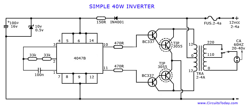
An article on how to create an inverter using a simple 40-watt inverter circuit diagram and schematics. This inverter converts 12 volts to 220 volts using the CD4047 integrated circuit. The described inverter circuit utilizes the CD4047 IC, which is...
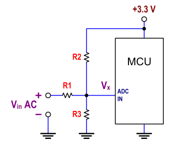
The ATtiny24 microcontroller's ADC is utilized to record an AC signal, which operates within a voltage range of 0 to 3.3V. A precision rectifier is employed to eliminate the negative portion of the signal. The circuit incorporates an LMC6484...
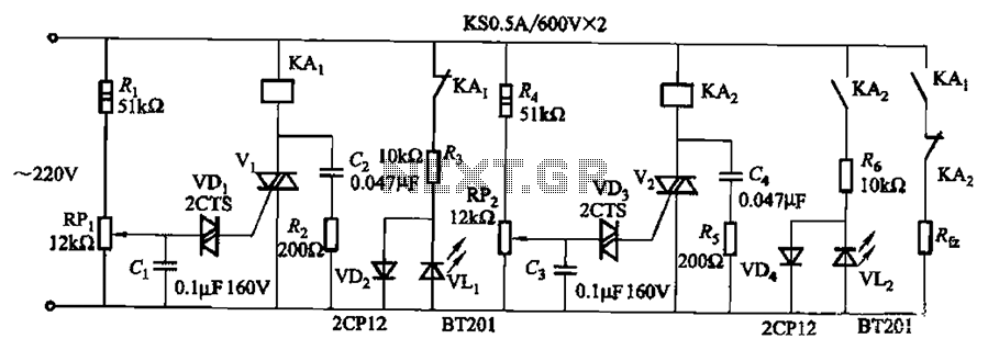
Bidirectional thyristor control. By adjusting potentiometers RPi and RPz, the lower and upper limit values can be changed. LEDs VLi and VL2 serve as indicators for low pressure and high pressure, respectively. The circuit utilizes a bidirectional thyristor to control...
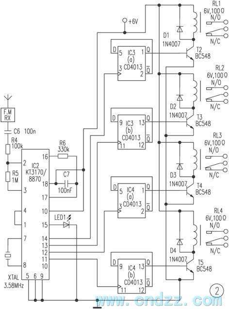
The remote control transmitter consists of a DTMF generator and an FM transmitter circuit. A UM91214B phone-specific integrated circuit (IC) is utilized to generate the DTMF signal, with a 3V power supply provided by a 3V zener diode (D1)....
This transmitter emits an FM signal within the 88 to 108 MHz frequency range, featuring a tone of 19 kHz. This tone can activate the FM MPX pilot carrier indicator, allowing interfacing with external devices. L4 is designed for...
This circuit is a touch-sensitive lamp delay switch characterized by minimal static power consumption. It utilizes an external switch terminal, which can directly replace a standard switch. The circuit features a novel precision voltage regulator integrated circuit, such as...