
Digital Volume Control

The circuit described is a digital volume control system that utilizes six integrated circuits (ICs) to manage audio levels electronically. The main components include a 555 timer configured as an astable multivibrator (IC1), which generates a square wave signal. The frequency of this signal can be modified by selecting appropriate resistor values (R44, R45) and a capacitor (C6), allowing for a period of 0.3 seconds as specified.
IC2 serves as a presetable up/down counter, which is essential for tracking the volume changes. In this configuration, the up mode increments the volume while the down mode decrements it, providing a straightforward user interface for volume adjustments. The counter's output is in Binary-Coded Decimal (BCD) format, making it suitable for digital applications.
Analogue multiplexers IC3 and IC4 play critical roles in the circuit. IC3 is utilized as a level indicator, likely providing visual feedback on the current volume level, while IC4 acts as a digital potentiometer, facilitating smooth transitions in volume levels without the mechanical wear associated with traditional potentiometers.
The system initialization requires the pressing of switch S1, which resets the entire circuit to a known state. Subsequently, switch S2 can be activated to enable the counting process, allowing the user to adjust the volume by counting the pulses generated by the 555 timer.
Finally, IC6 functions as an interface between TTL (Transistor-Transistor Logic) and CMOS (Complementary Metal-Oxide-Semiconductor) technologies, ensuring compatibility between different logic levels in the circuit. This integration of components results in an efficient and reliable digital volume control system suitable for various audio applications.Circuit of a digital volume control using six discrete ICs, including a 5V regulator, is presented. IC1 (555) is configured to function as astable flip-flop. Its frequency or period may be adjusted by proper choice of resistors R44, R45 and capacitor C6 combination. Here it is for 0.3 second period. IC2 is a presetable up/down counter. In this circuit up-mode is used for increasing and down-mode is used for decreasing the volume. IC3 and IC4 are 16-channel analogue multiplexers which function as analogue switches. Here IC3 is used as level indicator while IC4 is used as a potentiometer. Soon after the power is switched on, switch S1 is to be pressed to reset the whole system. When switch S2 is pressed, IC2 counts up the number of pulses and the result is available in the form of BCD output. IC6 is used as an interface between TTL and CMO 🔗 External reference
Related Circuits
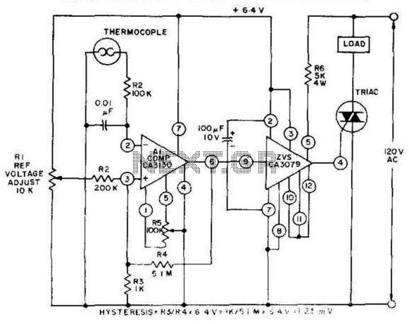
This control, featuring zero-voltage load switching, utilizes a CA3130 BiMOS operational amplifier and a CA3079 zero-voltage switch. The CA3130, functioning as a comparator, is particularly suited for comparing the low voltages produced by a thermocouple against an adjustable reference...
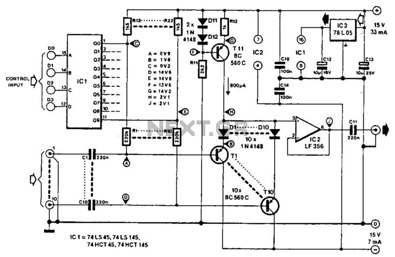
This circuit employs switched emitter followers instead of conventional analog switch CMOS chips, resulting in a more effective reduction of crosstalk between channels. It can manage up to 4 Vms with less than -80 dB crosstalk. The circuit design utilizes...
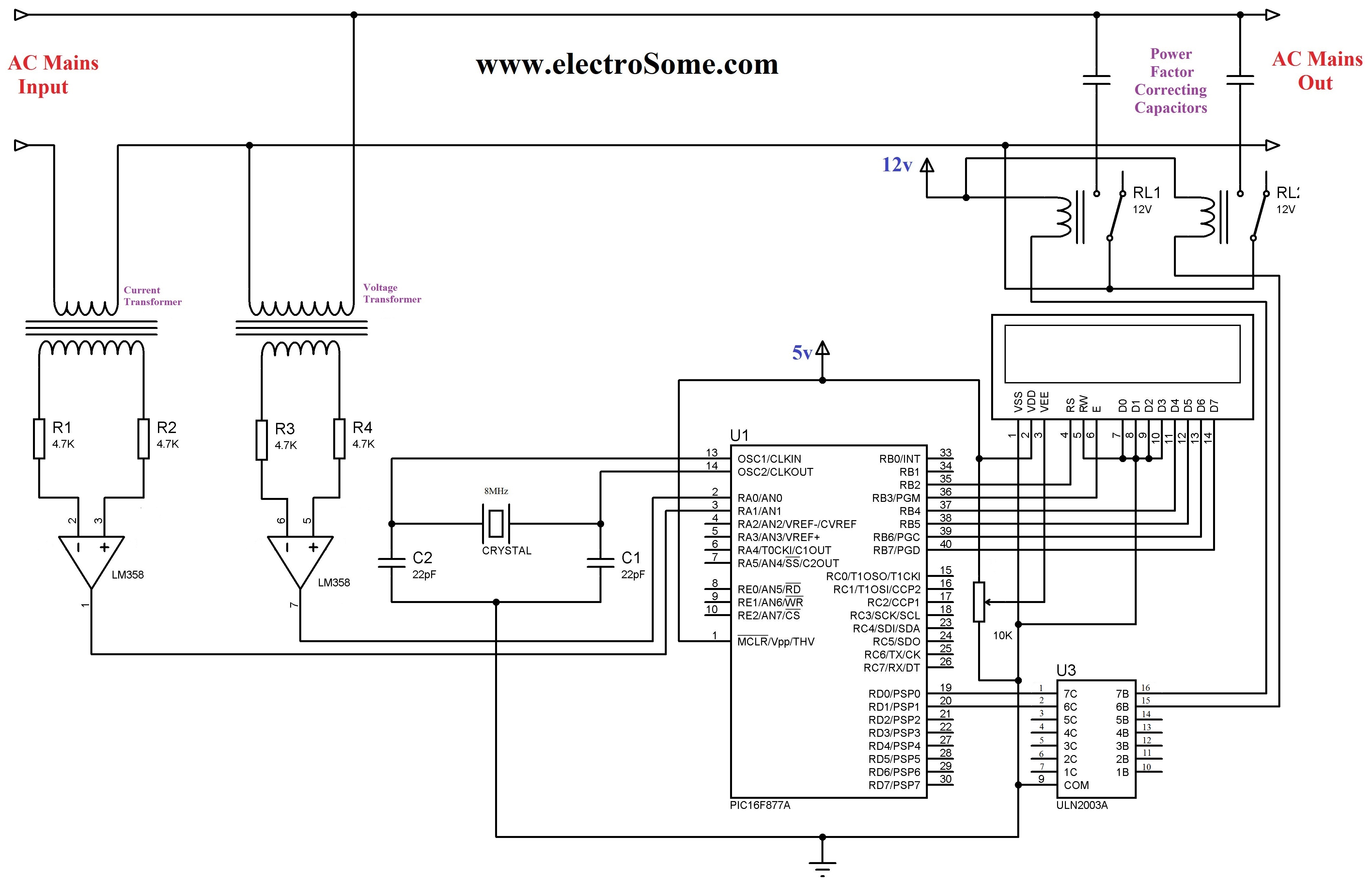
The 230 V, 50 Hz supply is stepped down using a voltage transformer, while a current transformer is utilized to extract the current waveforms. The output of the voltage transformer corresponds to the voltage across the load, and the...
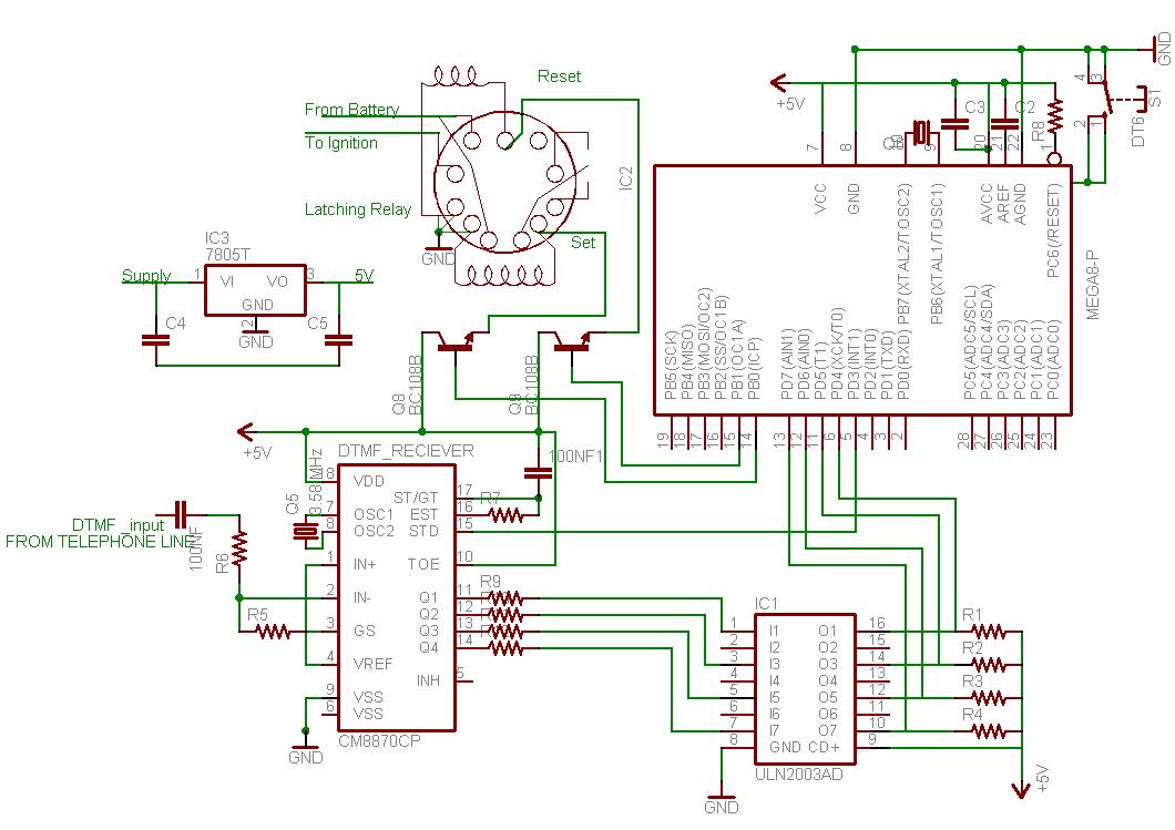
This document outlines the process of interfacing a microcontroller with a phone line. The tones generated when dialing numbers on a phone can be utilized to remotely control various devices. It provides guidance on incorporating Dual-Tone Multi-Frequency (DTMF) tones...
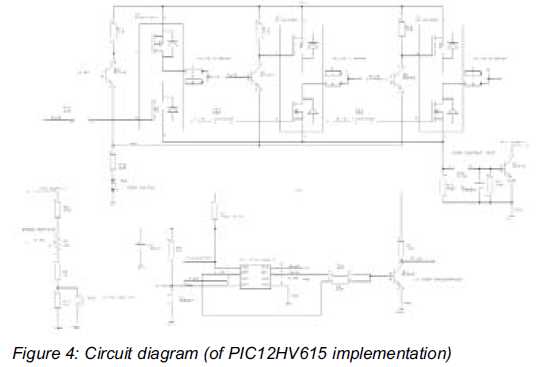
This article discusses a minimal resource microcontroller implementation for a three-phase Brushless DC (BLDC) motor, focusing on a closed-loop speed motor controller application based on a Microchip PIC12 device. It demonstrates how minimization techniques can reduce the number of...
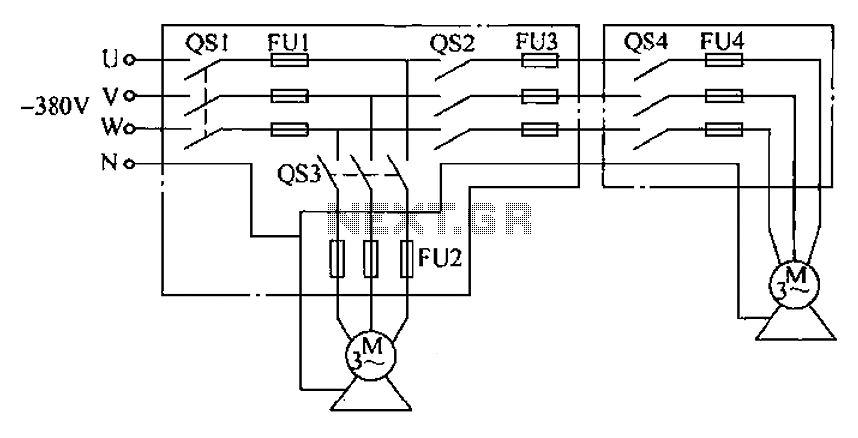
The agriculture and electrical power harrow plow power cord must consist of four rubber cables, with one core wire designated as the ground wire. The traction machine housing must be properly grounded. The two traction power machines are connected...