
digital multimeter for your car

A comprehensive electronic schematic can be derived from this project description, integrating several key components and functionalities. The core of the design is the ICL7107 ADC, which converts analog voltage levels into a digital format suitable for display on a seven-segment display. This ADC is typically paired with a common cathode or common anode seven-segment display, allowing for clear visual representation of the measured values.
The power supply section of the circuit is critical, as it provides the necessary voltage levels for the operation of the various components. The 7805 voltage regulator ensures a stable +5V output, while the 7660 or 7905 generates the required -5V from the available +5V or +12V sources, respectively. The inclusion of decoupling capacitors (100nF and 470µF) is essential for filtering out noise and stabilizing the power supply.
The stepper motor, functioning as a speed sensor, generates an AC signal that requires rectification. The diode bridge composed of four 1N4007 diodes converts this AC signal into a DC voltage, which is then smoothed by the 100nF capacitor. This rectified voltage can be fed into the ICL7107 for further processing or directly into the LM2917 for RPM calculations.
Calibration is a significant aspect of this design, as it ensures accurate readings from both the tachometer and speedometer. The use of trimmer potentiometers allows for fine-tuning of the voltage readings, ensuring that the output corresponds accurately to the engine speed and vehicle speed. The LM2917 provides an output voltage that is proportional to the frequency of the input signal, which is derived from the ignition coil, making it suitable for RPM measurement.
The LM35 temperature sensor adds another layer of functionality to the circuit, allowing for the monitoring of engine temperature. Its output voltage changes linearly with temperature, providing a straightforward method for temperature measurement. The sensor's placement in a drilled hole in the engine block ensures good thermal contact, while the use of epoxy glue secures it in place and protects it from environmental factors.
Overall, this circuit design presents a multifaceted approach to vehicle monitoring, combining digital tachometer and speedometer functions with temperature measurement capabilities. Each component's selection and configuration are crucial for ensuring reliable operation and accurate readings across the various monitored parameters.digital tachometer & speedometer using seven segment display, but I failed to do it the right way. The circuits I used before were too crowded with ICs & other components. Then I managed to build the LED tachomter. Later, I got a stepper motor & used it as a speed sensor to build the LED speedometer successfully, too. The ICL7107 came to my mind. A simple, old yet reliable analog to digital converter used in digital voltmeter circuits. VOLTMETER Why not to build a voltmeter, then calibrating it to get the car speed from my stepper motor & get the RPM from my LM2917 voltage output What about adding a digital thermometer using the LM35 temperature sensor Photo paper with desried print (use two copies one over each other, in the rear one cut the yellow rectangles facing the LEDs). I prefer matte over glossy photo paper btw. I started with the main circuit (the ICL7107 voltmeter). The ICL7107 is an analog to digital converter interfaced to seven segment display. The 7660 provides the circuit with ( -5V) voltage from ( +5V ) input, you can use the 7905 for the same purpose (to get ( -5V ) from the ( +12V ).
Other components are really few. using the 7805 voltage regulator, two 100nF pol. capacitors & one 470uF electrolytic capacitor. adding a rectifier diode 1N4007 to the 12V input (from the car battery) From the stepper motor I mounted to my car`s transmission in the previous post. The current generated directly from a stepper motor is AC (alternating current). So, I added a simple diode bridge to get DC (direct current) from AC using four 1N4007 rectifer diodes & a 100nF capacitor for "smoothening" the output.
Adding 1. 5Mohm & 470Kohm trimmer potentiometer for calibration From the LM2917 pins No, 5&10. I made a small circuit powered with the same +5V supply. The circuit is similar to the one I used in the "LED tachometer" post. This gets the engine revolutions signal from the car`s igntion coil (high voltage input!). Calibration through the 220K trimpot. I used the LM35 digital centigrade temperature sensor. It`s 0. 5C accuracy, gives 10mV/1C change. The LM35DZ variant operates between 0-100C only. The LM35AH operates between -55 to 150C. This is powered from the same +5V power supply. After soldering the terminals. I covered them & the wire with epoxy glue which is non-conductive to electricity & water proof. I used a 100Kohm trimpot for calibration. I put the LM35 under my tongue, waited till it gets a stable reading then calibrated it to 37C (assuming I have a normal temperature :) ). Pass it to boiling water & calibrate it too 100C. The sensor should be fixed well in a site of good thermal conductivity to get the engine temperature.
I drilled a hole in part of my engine block (steel), filled it with epoxy glue & dipped the LM35 in. You may prefer to use this sensor to get the coolant temperature. I will add to sensors, one for ambient temperature & the other for the in-car temperature. 🔗 External reference
Related Circuits
This is a simple 3-digit digital voltmeter. The PIC16F676 microcontroller is utilized to read an analog signal (voltage) and display the value on a 3-digit 7-segment display. It can also measure DC current using a parallel Rshunt, although that...

Designing and building a USB sound card has become straightforward with the PCM2702 integrated circuit from Texas Instruments. The PCM2702 is a 16-bit digital-to-analog converter featuring two digital-to-analog output channels. Its integrated interface controller adheres to USB 1.0 standards....

The trembler (motion-activated) switch triggers an alarm for 5 seconds before automatically turning off. The circuit has a timeout period of 10 seconds to allow the trembler switch to stabilize. The trembler switch circuit operates by detecting motion through a...
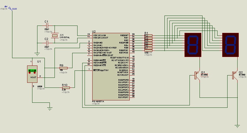
A digital thermometer is utilized for measuring room temperature. This project serves as a foundational exercise for beginners to comprehend the functions of various pins on the PIC16F877A microcontroller. The design incorporates the analog-to-digital conversion (ADC) capabilities of the...
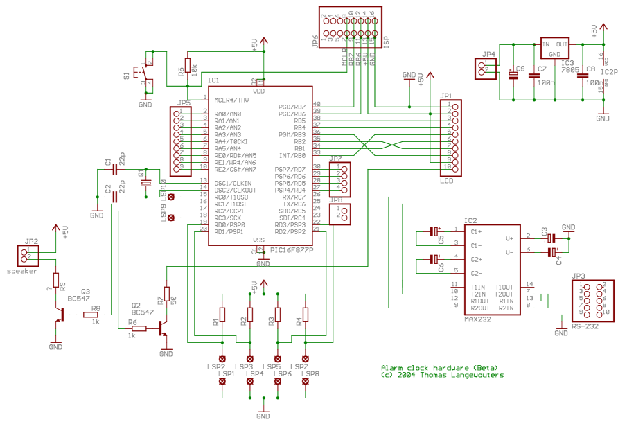
This project outlines a digital clock featuring an alarm function, utilizing a PIC16F877 microcontroller to achieve an accurate 1-second delay with Timer0 through Roman's zero error method. The time is displayed in large font on a 4G—20 character LCD,...
An electrocardiogram (ECG), also known as EKG (derived from the German term Elektro-Kardiographie), is an electrical recording of the heart utilized in diagnosing heart disease. This application employs a DrDAQ Data Logger to read and store electrocardiograms. British physiologist...