
Electrocardiagram (ECG / EKG) for DrDAQ Data Logger
 for DrDAQ Data Logger")
The ECG circuit design begins with the AD624AD Instrumentation Amplifier, which is chosen for its high common-mode rejection ratio and low noise characteristics, essential for accurately amplifying the small electrical signals generated by the heart. The self-sticking electrodes are strategically placed on the patient's skin to minimize motion artifacts and ensure reliable readings. The amplifier's gain can be adjusted to optimize the output signal for the data acquisition system.
The RG-174 coaxial cables used in the design are crucial for maintaining signal integrity. These cables are shielded to prevent electromagnetic interference, which could distort the ECG signal. The Lemo connectors facilitate secure connections, ensuring that the setup remains stable during operation.
Diode protection is implemented at the input stage of the amplifier to prevent any accidental high-voltage surges from damaging the sensitive electronics. This safety feature is particularly important in medical applications where patient safety is paramount.
The data acquisition system, utilizing the DrDAQ Data Logger, converts the amplified ECG signal into a digital format for analysis and storage on a laptop. This setup allows for real-time monitoring and long-term data collection, enabling healthcare professionals to review the patient's cardiac activity over time.
Overall, the described ECG circuit is a robust and effective solution for capturing and analyzing cardiac electrical signals, contributing significantly to the field of cardiology and patient care.An electrocardiogram or ECG (also known as EKG ” abbreviated from the German word Elektro-Kardiographie), is an electrical recording of the heart and is used in the investigation of heart disease. This application makes use of a DrDAQ Data Logger to read and store electrocardiograms. British physiologist Augustus D. Waller was the pioneer of ele ctrocardiography and in 1887 published the first human electrocardiogram. Yet in 1911 Waller said, "I do not imagine that electrocardiography is likely to find any very extensive use in the hospital. It can at most be of rare and occasional use to afford a record of some rare anomaly of cardiac action.
" However, just 13 years later, the Nobel Prize in Medicine was awarded to Dutch physiologist Willem Einthoven, who transformed this curious physiologic phenomenon into an indispensable clinical recording device that is still used today. The electrocardiogram, or ECG / EKG is a surface measurement of the electrical potential generated by electrical activity in cardiac tissue.
Current flow, in the form of ions, signals contraction of cardiac muscle fibers leading to the heart`s pumping action. The ECG is a valuable, non invasive diagnostic tool which was first put to clinical use in 1913 with Einthoven`s invention of the string galvanometer.
The results below show a reproduction of one of Einthoven`s original traces. Einthoven`s recording is known as the "three lead" ECG, with measurements taken from three points on the body (defining the "Einthoven triangle" ” an equilateral triangle with the heart at the centre. ) The difference between potential readings from L1 and L2 is what is used to produce the output ECG trace.
The L3 connection establishes a common ground for the body and the recording device (oscilloscope. ) Establishing the correspondence between the ECG trace and the electrical events in the heart is known as the inverse problem of electrocardiology: solving for the electric sources from the potential generated by those sources on the surface of the body. The ECG device was constructed based on the "Amateur Scientist" article by Shawn Carlson that appeared in the June 2000 issue of Scientific American.
That article describes the layout for a circuit based on an instrumental amplifier that can be used to measure the ECG. The circuit was built with some modifications as described below, and a DrDAQ data acquisition card was used to read out the output signal into a laptop, which effectively functions as a storage scope.
The basic setup is illustrated below. As previously mentioned, the electronic circuit for the ECG application is similar to the one described in Shawn Carlson`s Scientific American article. The circuit diagram is shown below. At the heart of it is an AD624AD Instrumentation Amplifier from Analog Devices. The amplifier takes inputs from self-sticking electrodes that are attached to the body of the subject whose ECG is being taken.
Because the signals are small, and the amplifier can be susceptible to various noise sources, it is important for the cables connecting the electrodes to the inputs of the circuit (shown as the blue, red and green circles in the diagram) to be (1) as short as possible and (2) well shielded. RG-174 50 Ohm coaxial cables with lemo connectors were chosen as these cables are good to use for this project because they are sturdy, yet thin and light, and the lemo connectors are easy to plug and unplug into the aluminum sheet metal box that was used to house the circuit.
Because of the safety issues associated with electrically connecting a person to an electronics device that runs off a significant power source, diode protection was added to the inputs to the amplifier. The circuit shown above only runs off of two 9 volt batteries, which themselves don`t constitute a "significant power source", however an oscilloscope or computer to which the output of the amplifier is connected wi
🔗 External reference
Related Circuits
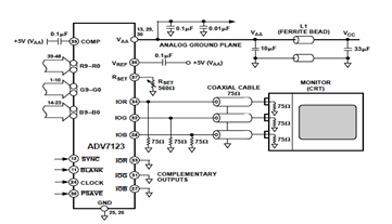
This digital-to-analog converter (DAC) integrated circuit is designed for optimal noise performance, minimizing both radiated and conducted noise. A recommended connection diagram for the ADV7123 is depicted in the following schematic diagram. According to the ADV7123 datasheet, this device...
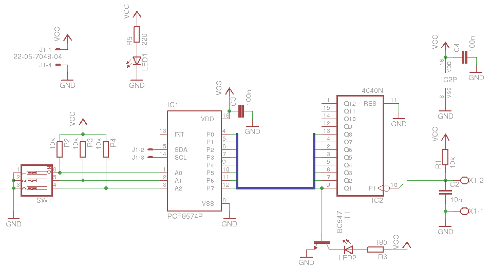
The board is relatively simple and is based on a PCF8574, which provides the output of a CD 4040 counter to the I2C bus. A DIP switch is included to select the PCF8574 address, along with some LEDs for...
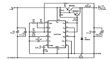
The schematic diagram below illustrates a 5V/1A Step-Down Switching Regulator utilizing the LM2524D Regulating Pulse Width Modulator (PWM). Additional parameters, PC board layout, stuffing diagram, and more information can be found in the LM2524D datasheet. The circuit design features the...
The Wireless Keylogger consists of two main building blocks: the transmitter and the receiver. The actual keylogging takes place in the transmitter, which is in fact a PS/2 hardware keylogger, with a built-in 2.4 GHz wireless module. Captured keystroke...
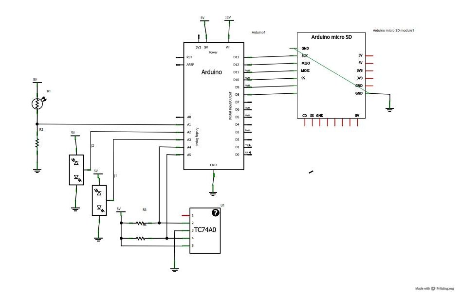
Now that the basics have been covered in tutorials 1-10, it is time to pursue more complex projects. In this episode, an SD card shield from cooking-hacks.com will be utilized to create a data logger. The process of reading...
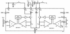
A constant off-time control that provides high efficiency over a wide range of output current can be utilized by the LT3463A dual micropower DC/DC converters with internal Schottky diodes, as detailed in the following circuit diagram and the datasheet. The...