
USB sound card

The PCM2702 integrated circuit is a versatile solution for creating USB sound cards, leveraging its compliance with USB 1.0 standards to ensure compatibility with a wide range of devices. The 16-bit digital-to-analog conversion capability allows for high-quality audio output, making it suitable for various applications, including personal computers and embedded systems.
The circuit's plug-and-play functionality simplifies integration into existing systems, as it eliminates the need for additional driver installations. This feature is particularly advantageous for users who require quick setup and compatibility with different operating systems. The support for multiple sampling rates enables the PCM2702 to cater to various audio formats, enhancing its versatility.
The on-chip clock generator facilitates synchronization of digital audio data, while the digital attenuator allows for precise control over audio output levels. The presence of playback, suspend, zero, and mute flags provides additional control features that can be utilized in software applications to manage audio playback effectively.
The circuit design includes critical connections such as the D+ and D- pins, which are essential for USB data transfer. The output audio signals are accessed via the VOUTL and VOUTR pins, providing left and right channel outputs for stereo audio. The incorporation of a 12 MHz crystal oscillator ensures stable operation and accurate timing for the digital-to-analog conversion process.
Powering the circuit through the USB connection not only simplifies the design but also ensures that the device remains portable and easy to use. The use of LDO voltage regulators to derive the necessary operating voltages from the USB port allows for efficient power management, ensuring that the circuit operates reliably under various conditions. Overall, the PCM2702 integrated circuit represents a robust and efficient solution for USB audio applications.Designing and building a USB sound card is no longer a head ache because we have got the PCM 2702 integrated circuit from Texas Instruments. The PCM2702 is an integrated 16 bit digital to analog converter that has two digital to analog output channels.
The integrated interface controller of PCM2702 is compliant to the USB 1. 0 standards. The IC can handle sampling rates of 48 KHz, 44. 1 KHz and 32 KHz. The IC also has a number of useful features like on-chip clock generator, digital attenuator, play back flag, suspend flag, zero flag, mute function etc. The most interesting thing is that this circuit is plug & play and doesn`t need any driver software for Windows XP and Windows Vista operating systems.
The circuit gets control data and audio data from the USB through the D+ and D- pins of the PCM2702 all the data transferring is carried out at full speed. The decoded audio signals will be available at the VOUTL and VOUTR pins of the IC. The 12MHz crystal is connected between the XT0 and XT1 pins of the IC. The VBUS (USB bus power) pin and DGND (digital ground) pins of the IC are connected to the +5V and ground pins of the USB respectively.
The circuit requires +5V DC and +3. 3V DC for operation and both of these voltages can be derived from the USB port using LDO (low drop out) voltage regulators (not shown in circuit). 🔗 External reference
Related Circuits
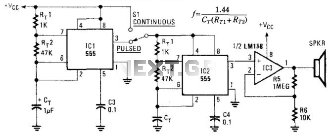
This circuit utilizes two NE555 timer IC devices to generate either pulsed or continuous ultrasonic signals. The values of CT for both pulse rate and ultrasonic frequencies can be calculated accordingly. SPKR refers to a small hi-fi tweeter. The circuit...

A SIM card, also known as a Subscriber Identity Module, is a smart card that stores data from a cellular phone. This data includes identity, location, phone number, network authorization data, personal security keys, contact lists, and stored text...
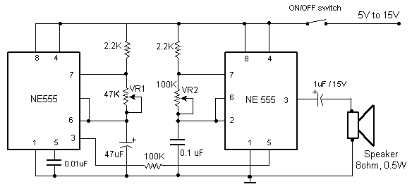
This circuit produces the famous Big Ben sound. It produces the "ding dong" sound when switched ON. Basically, the circuit alternates between two frequencies which are adjustable. This produces the "ding-dong" sound. The first IC (left) oscillates at about...
An electrocardiogram (ECG), also known as EKG (derived from the German term Elektro-Kardiographie), is an electrical recording of the heart utilized in diagnosing heart disease. This application employs a DrDAQ Data Logger to read and store electrocardiograms. British physiologist...
For simple electronic circuits, it may be sufficient to gain qualitative insights on dedicated electrical signals. This interface circuitry allows the line-in input of a standard PC sound card to be utilized as a 2-channel oscilloscope. Although this setup...
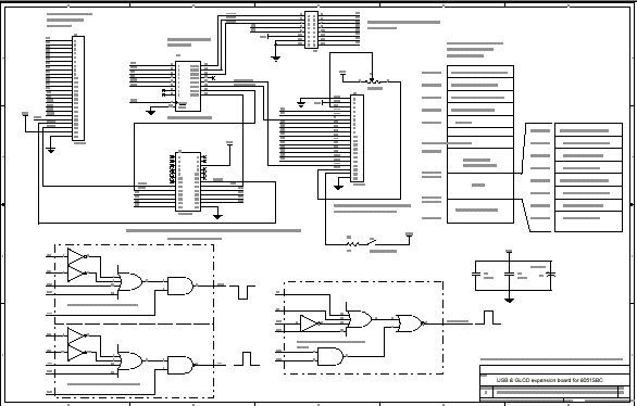
8051SBC USB and GLCD Expansion Board, electronic circuit schematic wiring diagram for the 8051SBC USB and GLCD Expansion Board. The 8051SBC USB and GLCD Expansion Board is designed to enhance the functionality of the 8051 microcontroller system by providing additional...