Digital Red Light Jump Checking System with RF Transmitter
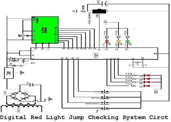
A digital red light jump checking system with an RF transmitter. This project allows for the tracking of vehicles that run red lights by capturing their license plate numbers and the time of the violation.
The digital red light jump checking system is designed to enhance traffic management and law enforcement by monitoring and recording instances of vehicles violating traffic signals. The system employs an RF transmitter to communicate data wirelessly, facilitating real-time tracking and documentation of violations.
The core components of the system include a camera module for capturing images of vehicles at intersections, an image processing unit for analyzing the captured images to extract license plate numbers, and a microcontroller for managing data processing and communication. The RF transmitter is integrated to send the violation data, including the license plate number and timestamp, to a central monitoring system or law enforcement agency.
In operation, when a vehicle crosses the intersection during a red light, the camera captures an image of the vehicle. The image processing unit utilizes optical character recognition (OCR) algorithms to identify and extract the license plate number from the image. Simultaneously, the system logs the exact time of the violation. This information is then transmitted via the RF transmitter to the designated receiver, which could be a server or a handheld device used by law enforcement personnel.
The system's design emphasizes reliability and accuracy, ensuring that instances of red light jumping are documented with clear photographic evidence and precise timestamps. This data can be utilized for issuing fines, analyzing traffic patterns, and improving overall road safety. The integration of RF technology allows for seamless data transfer, minimizing the need for physical connections and enhancing the system's flexibility in deployment.digital red light jump checking system with RF transmitter. By implementing this project we can trace the red light jumping car with number and the time 🔗 External reference
