
Digital weight scale

The circuit operates by integrating a potentiometer, which serves as a variable resistor that changes its resistance based on the position of its wiper. When a weight is applied to the scale, the wiper moves, altering the resistance and consequently the voltage output across the potentiometer. This voltage change is directly proportional to the weight applied, allowing for accurate weight measurement.
The output voltage from the potentiometer is then fed into an analog-to-digital converter (ADC). The ADC translates the analog voltage signal into a digital format suitable for processing. This digital signal is subsequently decoded by a microcontroller or a dedicated decoder circuit, which interprets the value and prepares it for display.
The microcontroller interfaces with a numeric display, typically a seven-segment display, to present the weight measurement in a user-friendly format. The display is updated in real-time, providing immediate feedback on the weight applied to the scale. Additional components such as resistors and capacitors may be employed in the circuit to ensure stability and accuracy in readings, as well as to filter any noise from the voltage signal to enhance the precision of the weight measurement system.
Overall, this circuit design effectively combines mechanical and electronic components to create a reliable weight measurement device.This circuit employs a potentiometer as the weight sensing element. An object placed upon the scale displaces the potentiometer wiper, an amount proportional to its weight Conversion of the wiper voltage to digital information is performed, decoded, and interfaced to the numeric display.
Related Circuits
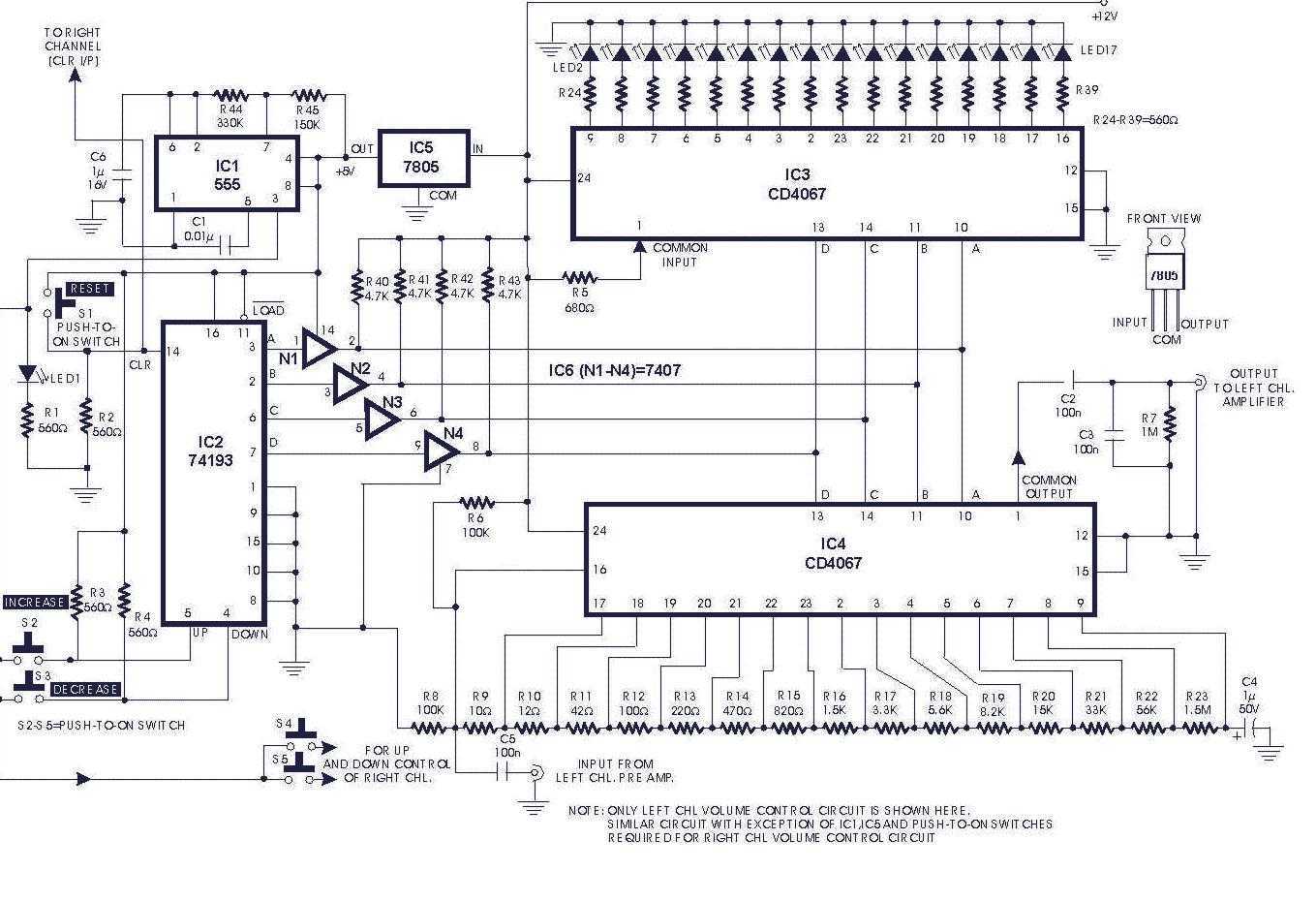
Circuit of a digital volume control using six discrete ICs, including a 5V regulator, is presented. IC1 (555) is configured to function as astable flip-flop. Its frequency or period may be adjusted by proper choice of resistors R44, R45...

This circuit is intended for precision centigrade temperature measurement, with a transmitter section converting to frequency the sensor's output voltage, which is proportional to the measured temperature. The output frequency bursts are conveyed into the mains supply cables. The...
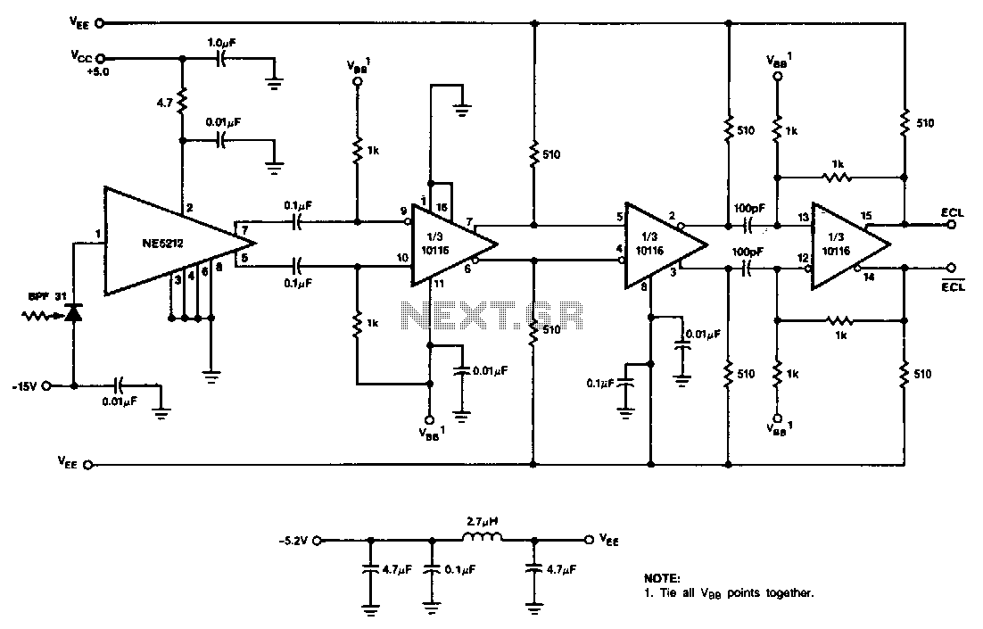
This receiver utilizes the NE5212, the Signetics 10116 ECL line receiver, and the Phillips/Amperex BPF31 pin diode. The circuit is a capacitor-coupled receiver that employs positive feedback in the final stage to introduce hysteresis. The level of hysteresis can...
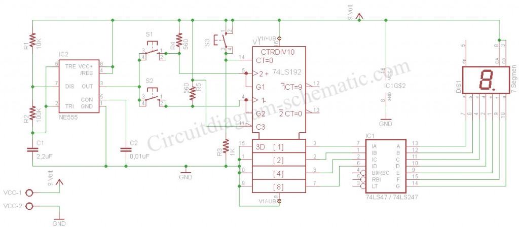
The digital scoreboard circuit is designed to display numerical values ranging from 0 to 9 on a 7-segment display. This display utilizes a common anode configuration. The digital scoreboard circuit operates by controlling a 7-segment display that utilizes a common...
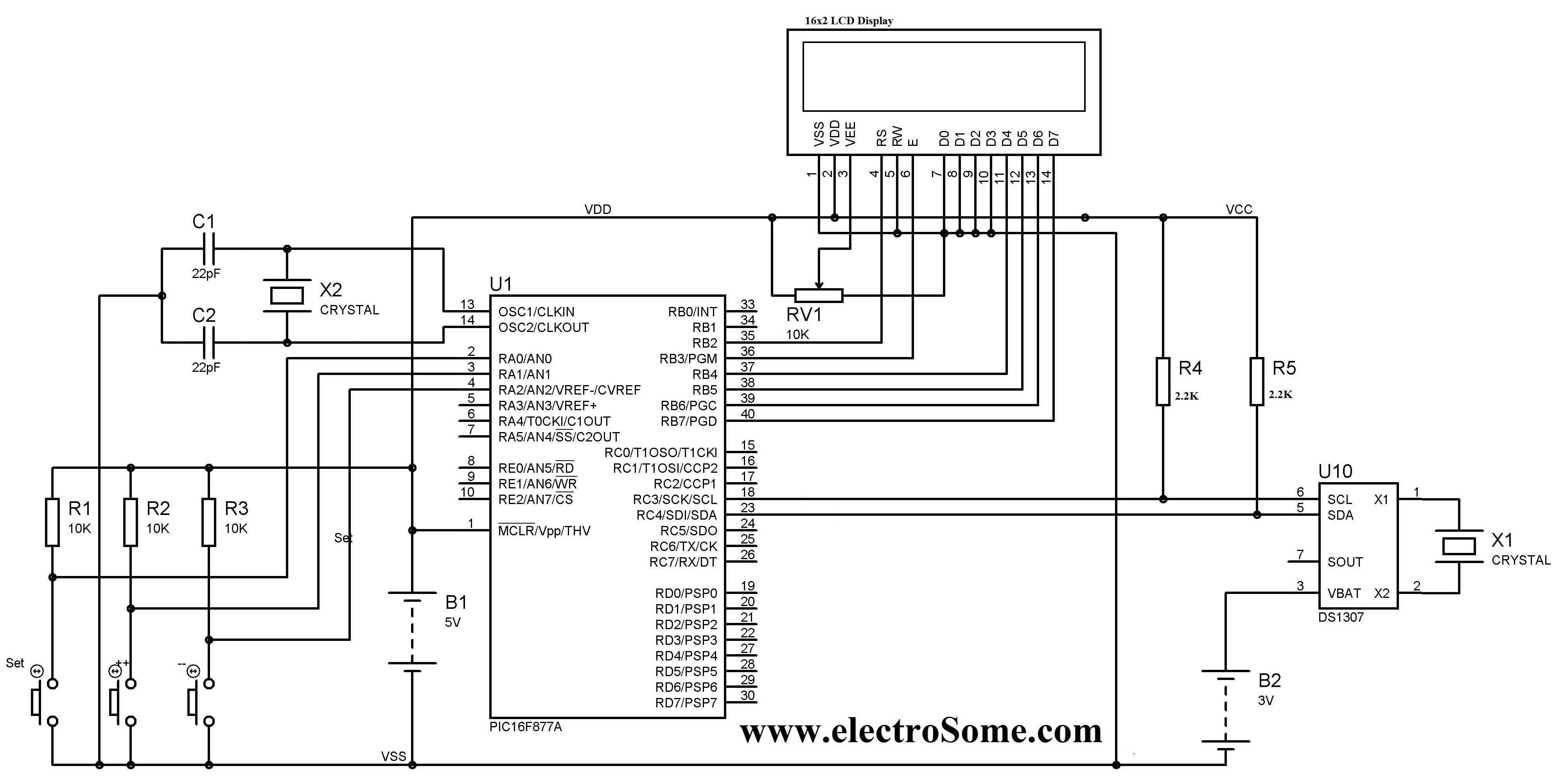
A digital clock can be constructed using a PIC microcontroller, DS1307 real-time clock (RTC), and a 16x2 LCD display. The DS1307 RTC operates in either 24-hour or 12-hour mode with an AM/PM indicator. It adjusts automatically for months with...
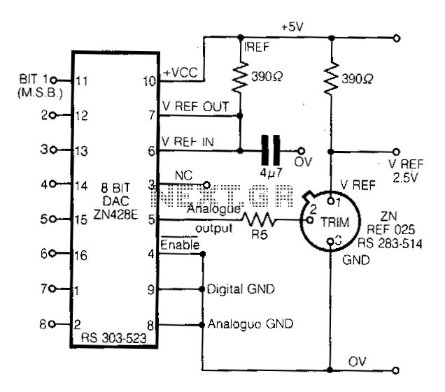
This circuit demonstrates a straightforward approach to achieving a voltage reference that can be adjusted using an 8-bit Digital-to-Analog Converter (DAC) equipped with an integrated voltage reference. The analog output from the DAC controls the trim pin of the...