
Speech Recognition Circuit


The circuit utilizes the HM2007 speech recognition chip, which is designed for manual operation through a user-friendly interface comprising a keypad and a digital display. Upon powering the circuit, the HM2007 performs a self-check on the static RAM to ensure functionality. A successful check is indicated by the display showing "00" and the activation of the red LED, which signifies that the system is ready to receive commands.
To initiate the training process, the user selects a word number from 1 to 40 using the keypad. Once a number is pressed, the red LED turns off, and the selected number is shown on the digital display. The user must then press the "#" key to signal the HM2007 to enter training mode. In this mode, the red LED reactivates, indicating that the system is prepared to record a new voice command.
The user must speak the desired word clearly into the microphone. The system acknowledges the input by momentarily turning off the LED, which serves as a confirmation that the word has been successfully recorded. The training process can be repeated for additional words by following the same steps: selecting a number, pressing "#", and speaking the word.
The circuit is designed to continuously listen for commands after training. When a trained word is spoken into the microphone, the HM2007 processes the input and displays the corresponding word number on the digital display. This feature allows for effective testing and validation of the recognition capabilities of the circuit. For example, if the word "directory" has been trained as the 25th word, saying "directory" will prompt the display to show the number 25, confirming successful recognition. The system's flexibility allows users to train fewer than the maximum of 40 words, accommodating a variety of applications and user preferences.The demonstration circuit operates in the HM2007's manual mode. This mode uses a simple keypad and digital display to communicate with and program the HM2007 chip. When the circuit is turned on, the HM2007 checks the static RAM. If everything checks out the board displays "00" on the digital display and lights the red LED (READY). It is in the "Ready" waiting for a command. To train the circuit begin by pressing the word number you want to train on the keypad. The circuit can be trained to recognize up to 40 words. Use any numbers between 1 and 40. For example press the number "1" to train word number 1. When you press the number(s) on the keypad the red led will turn off. The number is displayed on the digital display. Next press the "#" key for train. When the "#" key is pressed it signals the chip to listen for a training word and the red led turns back on. Now speak the word you want the circuit to recognize into the microphone clearly. The LED should blink off momentarily, this is a signal that the word has been accepted. Continue training new words in the circuit using the procedure outlined above. Press the "2" key then "#" key to train the second word and so on. The circuit will accept up to forty words. You do not have to enter 40 words into memory to use the circuit. If you want you can use as many word spaces as you want. Testing Recognition The circuit is continually listening. Repeat a trained word into the microphone. The number of the word should be displayed on the digital display. For instance if the word "directory" was trained as word number 25. Saying the word "directory" into the microphone will cause the number 25 to be displayed. 🔗 External reference
Related Circuits
The NE555 circuit implementation involves various connections and configurations. The circuit is designed with a supply voltage (Vcc) of +11V. The input terminal (pin 3) serves as a reset pin, and the relay and motor components are integrated into...
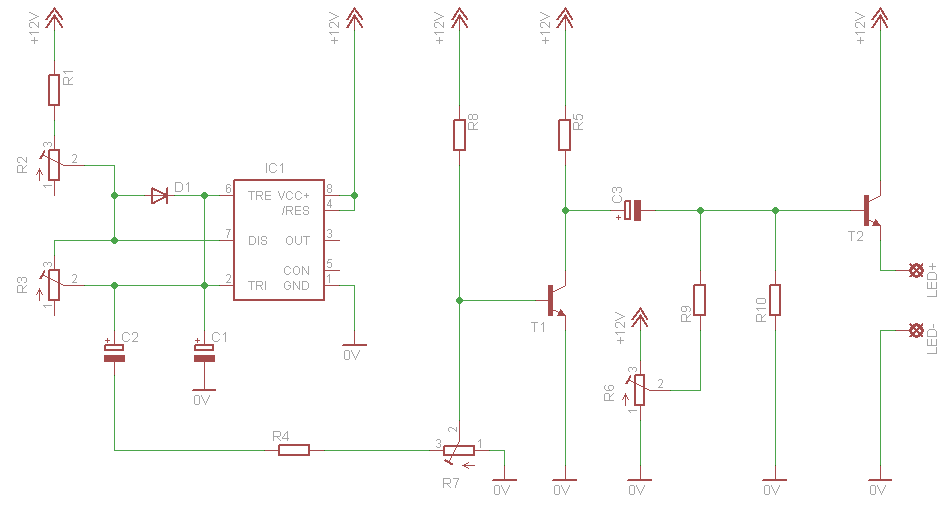
This circuit simulates a breathing or pulsing LED using a 555 timer chip. It has gained popularity, receiving numerous comments and emails from users who successfully built the circuit, as well as feedback from those who encountered difficulties when...
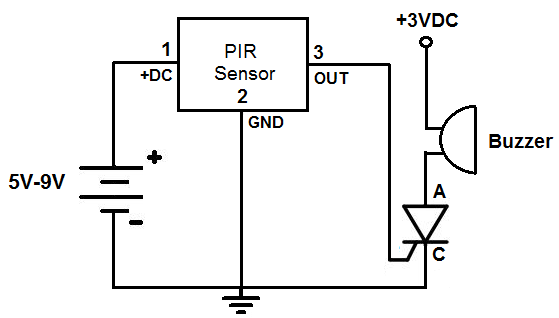
This is an alarm circuit that activates when motion is detected. Upon detection, the circuit triggers an alarm buzzer, which remains activated until the power is disconnected. This type of alarm circuit is commonly used to monitor areas for...
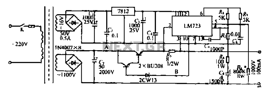
Battery forklifts are commonly used as stacking and handling tools in railway stations, docks, and warehouses. The battery shape and electrical control circuitry are depicted in the schematic. The system consists of batteries connected in series to form a...

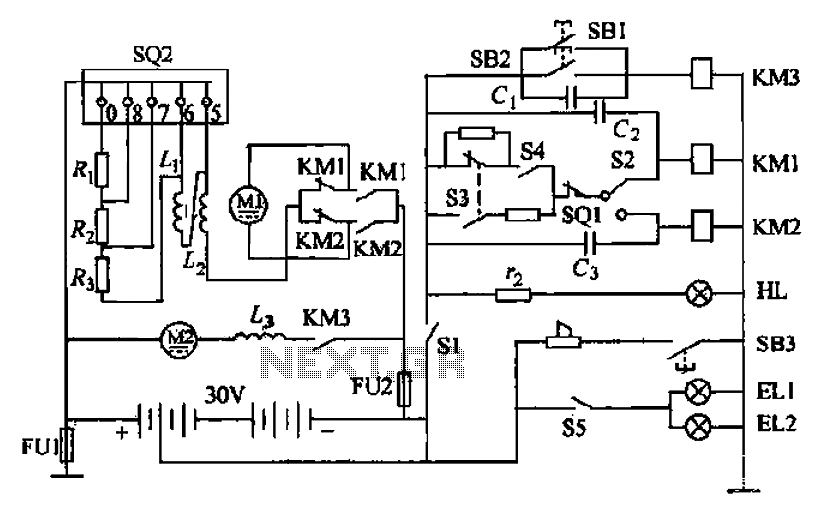
The utility vehicle anti-theft alarm circuit consists primarily of two main components essential for its operation. The security circuit is activated when the vehicle owner departs from the vehicle, utilizing an anti-theft switch (S B) to engage the alarm...
Light flashing circuit. This circuit is designed to create a small lamp that flashes with a signal at a rate of one flash per second, controlled by adjusting the lamp voltage through resistor R1. The rate is adjustable to...