
Tone probe for testing digital ics

The probe's input circuit is designed to monitor electrical signals and provide auditory feedback regarding their levels. It operates by utilizing a comparator circuit that evaluates the input voltage against predefined thresholds. When the input voltage falls below 0.8 V, the circuit activates a low-frequency oscillator, producing a low-pitched tone. Conversely, when the signal exceeds 2 V, the circuit switches to a high-frequency oscillator, generating a high-pitched tone.
The circuit typically consists of several key components: a voltage divider to scale the input signal, an operational amplifier configured as a comparator, and a piezoelectric speaker or buzzer for sound output. The voltage divider ensures that the input signal is within the operational range of the comparator, while the operational amplifier provides the necessary gain and switching capability.
Additionally, the design may include a microcontroller to enhance functionality, allowing for adjustable thresholds, signal processing, and possibly visual indicators, such as LEDs, to accompany the audible tones. This combination of sound and visual feedback aids in the effective monitoring of signal conditions in various electronic applications, such as troubleshooting and maintenance tasks. The tone probe serves as a valuable tool for engineers and technicians, providing immediate and intuitive feedback on signal status. The probe's input circuit senses the condition of the signal and produces either a low-pitched tone for low-level signals (less than 0.8 V) or a high-pitched tone for high-level signals (greater than 2 V). The tone probe uses sound to tell the status of the signal being probed.
Related Circuits
Security is a prime concern in our day-to-day life. Everyone wants to be as much secure as possible. An access control for doors forms a vital link in a security chain. The microcontroller based digital lock for Doors is...
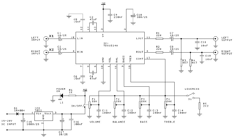
Preamplifier and tone control circuit based on the TDA1524A. The tone control circuit module is included in this preamplifier circuit, allowing for direct connection of the output channels to a stereo power audio amplifier circuit. This RIAA stereo preamplifier...

A digital stopwatch or digital timer circuit schematic is constructed using the timer IC LM555 and the 4-digit counter IC MM74C926, which is paired with a multiplexed 7-segment LED display. The digital stopwatch circuit utilizes the LM555 timer IC configured...
Phone In Use Indicator Electronics Project using 5 resistors, 2 NPN transistors, 4 diodes, and 2 light-emitting diodes. The Phone In Use Indicator is an electronic project designed to visually indicate when a telephone line is active. This circuit employs...
This tester is designed to locate stray electromagnetic (EM) fields. It will easily detect both audio and RF signals up to frequencies of around 100kHz. Note, however that this circuit is NOT a metal detector, but will detect metal...
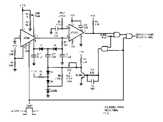
The simple 4-digit converter circuit has an output count of 1, designed to operate within a frequency range of f-IMHz to 10.000. All diodes used in the circuit are IN4146, and the capacitors are made of `POLYSTYRENE` NPO. The...