
digital thermometer

The digital thermometer circuit using an LM35 temperature sensor and a 7-segment display is a straightforward yet effective project suitable for various applications. The LM35 is a precision temperature sensor that provides an output voltage proportional to the temperature in degrees Celsius. It has a linear output of 10 mV/°C, making it easy to interface with microcontrollers.
The schematic consists of the following key components:
1. **LM35 Temperature Sensor**: This component is the core of the thermometer. It outputs a voltage that increases linearly with temperature. The output pin is connected to an analog input of a microcontroller (such as an Arduino) for temperature reading.
2. **Microcontroller**: A microcontroller is required to process the analog voltage from the LM35. It converts the voltage to a temperature reading using an Analog-to-Digital Converter (ADC). Popular choices include Arduino Uno or ATmega328 for their ease of use and extensive libraries.
3. **7-Segment Display**: This display consists of multiple LEDs arranged in a figure-eight pattern, allowing for the representation of numerical digits. To display the temperature, a common cathode or common anode 7-segment display can be utilized, depending on the design requirements.
4. **Resistors**: Current-limiting resistors are necessary for the 7-segment display to prevent excessive current from damaging the LEDs. The values of these resistors can typically be calculated based on the supply voltage and the forward voltage of the LEDs.
5. **Power Supply**: A suitable power supply is required to power the circuit. This could be a battery or a regulated DC power supply providing a voltage compatible with both the microcontroller and the 7-segment display.
The code for the microcontroller will involve reading the analog value from the LM35, converting it to a temperature reading, and then displaying that value on the 7-segment display. The code should include proper initialization of the ADC, reading the sensor value, and converting the voltage to temperature using the formula:
Temperature (°C) = (V_out / 10 mV).
The conversion will then be formatted to display on the 7-segment display, which may require multiplexing if multiple digits are used. The implementation can be achieved using libraries available for the selected microcontroller platform, simplifying the programming process.
This project serves as an excellent introduction to interfacing sensors with microcontrollers and displaying data, providing practical experience in electronics and programming.Can someone help me find a schematic and codes about a digital thermometer using a LM35 and 7 segment display(0 - 150.5 degree celcius)..the code must .. 🔗 External reference
Related Circuits
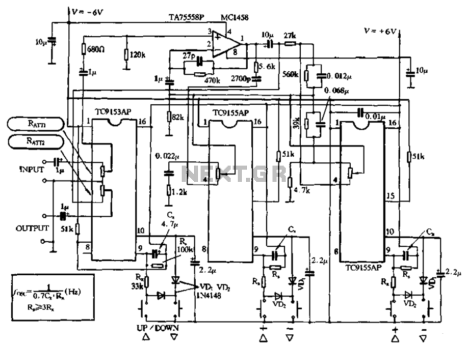
Figure 4-18 illustrates a volume potentiometer T (Xi 153AP) and a tone potentiometer T (155AP) that make up a volume and tone control circuit. This circuit includes Rx and Cx as clock oscillation elements, with values selectable based on...
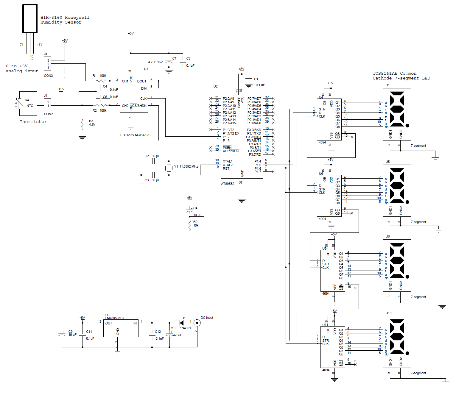
This circuit features a microcontroller AT89S52 thermometer paired with an LTC1298 12-bit ADC. The program is written in C language and incorporates digital filtering along with an interface for an LED display. The temperature readings have a sensitivity of...
By utilizing a reverse binary counter along with a binary-coded decimal (BCD) decoder, a step voltage can be generated, which can then be approximated to produce a sine wave signal with adequate accuracy for various applications. In the digital...
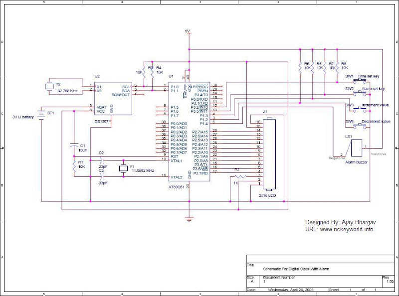
After the SCL line is high, the SDA line must be held low to indicate that the data being transmitted is legally binding. The data can only change when the SCL line is low. During the transfer of a...
By using the same circuit of the Digital Stopwatch 0-99sec, we can add an AND gate and transform the 0 to 99sec stopwatch to a 0 to 60sec stopwatch. We must find a way to control the RESET function...
This circuit uses a germanium diode (marked Ge) as a temperature sensor. I used an OA90 diode but others should do. The 'ring' of Tr1 and Tr2 bias each other. Tr1's collector current is stabilized by the 5v6 zener,...