
Schematics Ultra-Long Time Delay By IC Timer 555 PCB

The circuit employs the NE555 timer in a monostable configuration to generate a pulse when triggered. The duration of this pulse can be adjusted by varying the resistor R2 and the capacitor connected to the timing circuit. The output pulse from the NE555 is then fed into a CD4017 decade counter, which counts the pulses and provides an output after every ten pulses. This effectively extends the timing capability of the circuit, allowing for longer delays.
The S1 switch serves a critical role in the operation of the circuit. When in the Run position, the circuit operates normally, generating the time delays as designed. In the Reset position, the circuit can be reset, allowing it to be re-triggered without waiting for the previous cycle to complete.
The use of the 4017 counter is particularly advantageous as it provides multiple outputs, enabling the circuit to be used in applications where sequential timing is required. Each output from the 4017 can be utilized to trigger additional components or circuits, expanding the functionality of the delay circuit.
In summary, this circuit effectively combines the timing capabilities of the NE555 timer with the counting capability of the CD4017, allowing for precise control over long time delays in various electronic applications.This be the circuit delays to have for a long time. By use the integrated circuit Timer 555 or Ultra-Long Time Delay By IC Timer 555 by R2 use for fine the frequency of pulse from the integrated circuit NE555 bring divide by wasp with 4017 each 10 in the end the time delays to follow want. Part S1 for choose Reset or Run of the circuit. 🔗 External reference
Related Circuits
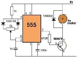
This project utilizes a 555 timer to control the speed of a 6-volt DC motor. Speed adjustment is achieved by rotating a 50 kΩ potentiometer either to the left or right. The circuit employs the 555 timer in astable mode,...

This is a simple touch switch circuit where the 555 timer is configured as a one-shot multivibrator triggered by touching the touch terminal. In monostable mode, the timer generates a fixed pulse of approximately 4 seconds whenever the trigger...
The crime prevention bell device produced approximately 20 years ago remains in active service. It has effectively deterred thieves on multiple occasions by triggering an alarm as they attempt to enter. The bell continues to ring, functioning as a...
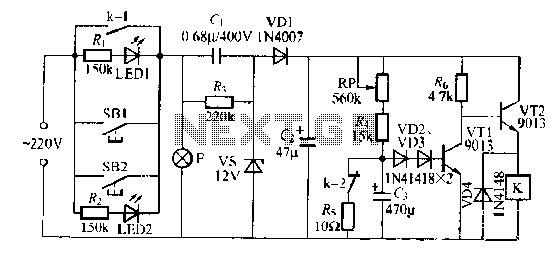
The lamp relay delay circuit is illustrated in Figure 7. Components S131 and SB2 are light buttons mounted in different locations. The lamp can operate with F. LEDs (LED1 and LED2) should be installed in SB1 and SB2 to...
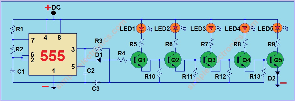
This project utilizes a 555 integrated circuit (IC) to create a sequential LED flashing effect. The configuration allows the LEDs to illuminate in a specific order, making it suitable for use as an indicator for vehicles and bicycles when...
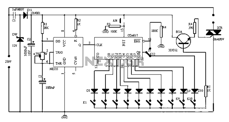
Figure 1-1 illustrates a general-purpose timer capable of timing intervals ranging from 5 minutes to 18 hours. The timing cycle can be adjusted to span from 5 minutes to 20 hours, with a maximum control time of 18 hours....