
Digital Thermometer using ATmegsa8 and LM335

The digital thermometer circuit utilizes the ATmega8 microcontroller, which serves as the central processing unit, and the LM335 temperature sensor, which provides an analog voltage output proportional to the temperature. The LM335 operates within a range of -40°C to +100°C, outputting 10 mV per degree Celsius.
To design the circuit, the following components are required:
1. **ATmega8 Microcontroller**: This 8-bit microcontroller features multiple analog-to-digital converters (ADCs) that can convert the analog voltage from the LM335 into a digital value. The microcontroller should be programmed to read the ADC values and convert them into temperature readings.
2. **LM335 Temperature Sensor**: This device will be connected to the microcontroller's ADC input. It is essential to ensure proper power supply and grounding to minimize noise in the readings.
3. **Display Module**: A suitable display, such as a 16x2 LCD or a seven-segment display, should be chosen to show the temperature readings. The microcontroller will control this display to present the processed temperature data.
4. **Resistors and Capacitors**: Additional passive components may be needed to filter the output from the LM335 and stabilize the power supply to the microcontroller.
5. **Power Supply**: A stable power source, typically 5V, is required to power the microcontroller and the sensor.
The circuit design should include connections from the LM335 to the ADC input of the ATmega8, a power supply circuit, and the interfacing of the display module. The microcontroller will need to be programmed in C or Assembly language to read the ADC values, convert them to temperature, and update the display accordingly.
In summary, the design of the digital thermometer involves selecting appropriate components, establishing connections, and programming the microcontroller to interpret temperature data and control the display output effectively.hello , I am planningto build Digital Thermometer using ATmegsa8 and LM335. Can Somebody tell me how should i go about ?? I want to display it on.. 🔗 External reference
Related Circuits
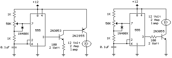
The schematic diagram illustrates a 12 Volt Car Lamp Dimmer Circuit Design utilizing a 555 Timer. This circuit can be employed to dim a standard 25-watt lamp. The 12 Volt Car Lamp Dimmer Circuit utilizes a 555 Timer in astable...
This is a dry cell battery charger circuit designed to charge batteries over a period of approximately 12 hours. When powered by a 9-volt supply, the circuit is configured to accommodate AA-sized batteries. If C or D-sized batteries are...
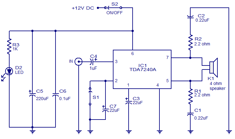
The audio amplifier presented here is based on the TDA7240 integrated circuit from ST Microelectronics. The TDA7240 is capable of delivering 20 watts of audio output power into a 4-ohm load. It requires a minimal number of external components...
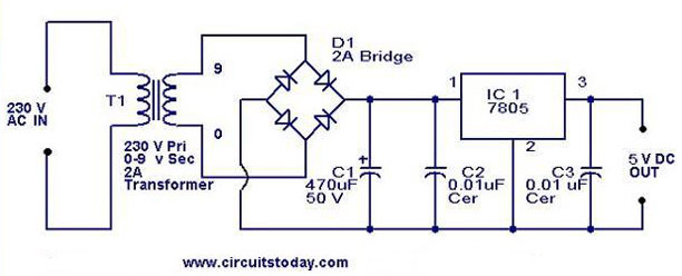
A 5V power supply using IC 7805 is designed and explained with a neat circuit diagram. The circuit for a 5V power supply utilizing the IC 7805 voltage regulator is a straightforward and efficient design that provides a stable output...
The following circuit illustrates a Mains Remote-Alert Circuit Diagram. Features include simple circuitry, with the transmitted signal being conveyed effectively. The Mains Remote-Alert Circuit is designed to provide a notification system that alerts users about the status of mains power....
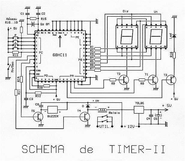
The timer is proposed an effective model for controlling an external load 8A/380V. Equipped with a 68HC11 mu.P associated with an 8 MHz crystal, it can get very precise programmable durations. Two lines are planned: from 0 to 99...