
Dry Cell Battery Charger Using LM741

This dry cell battery charger circuit is designed for efficient charging of standard batteries, particularly AA, C, or D sizes, with an emphasis on safety and functionality. The circuit operates from a 9-volt power supply, making it suitable for various applications. The resistor RX plays a critical role in current limiting; its value must be adjusted based on the size of the battery being charged to prevent overcurrent situations that could lead to battery damage. For C or D batteries, reducing RX to 68 ohms ensures appropriate charging current is provided.
The inclusion of the IC741 comparator circuit is pivotal for monitoring the charging process. This component compares the battery voltage against a predefined threshold of 1.6V, which is essential for determining when to cease charging. If the battery voltage drops below this threshold, the circuit is designed to disconnect the charging current, thereby preventing potential over-discharge and extending battery life.
The pulse oscillator, combined with the CMOS 4011, serves to control the charging process effectively. The transistor acts as a switch, allowing current to flow to the battery only when conditions are met, thereby optimizing the charging efficiency. The LED flasher acts as an indicator, alerting users when the charger is no longer functional or when the battery is fully charged.
In summary, this circuit not only facilitates the charging of dry cell batteries but also incorporates protective measures to enhance safety and prolong battery lifespan. The reuse of depleted batteries is encouraged, promoting sustainability and reducing waste. This design is ideal for hobbyists and professionals looking to implement a reliable battery charging solution.This is Dry Cell Battery Charger Circuit. That can use charger battery get that about 12 hour. When apply to power supply 9 volt the equipment that fix in the circuit use for size battery AA. If use the size C or D should devalue of Resistor RX down be 68ohm and should not lead battery come to serial while voltage in cell battery lower 1. 6V. The C omparator Circuit with (IC741) control Gate output from Pulse Oscillator at use the integrated circuit CMOS 4011 change Transistor that do infront charger battery until voltage tall 1. 6V Comparator Circuit more make LED Flasher warn know for protect Charger battery expire. The next time is if friends have Dry Cell Battery that use be finished already, don`t abandon, try apply new again yes.
🔗 External reference
Related Circuits
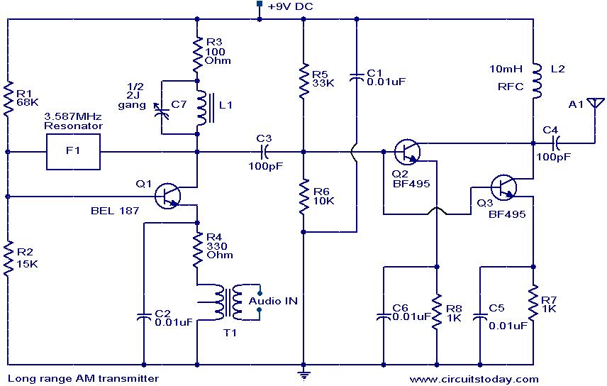
The circuit diagram of an AM transmitter circuit based on three transistors. With correct tuning and a matching antenna, the transmitter can effectively transmit amplitude-modulated signals. The AM transmitter circuit utilizes three transistors configured to amplify and modulate the input...
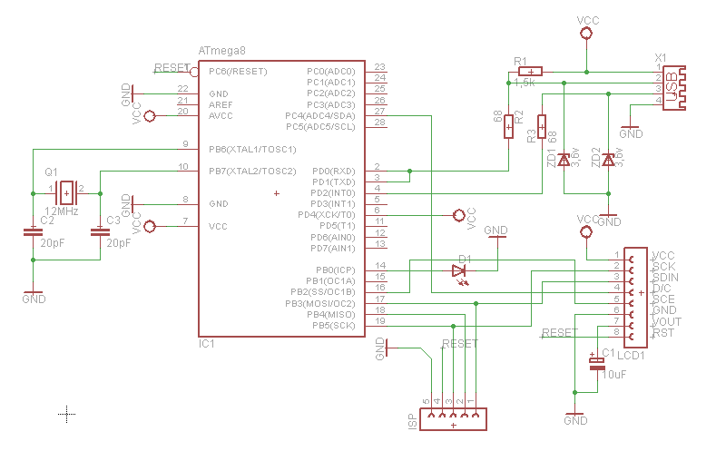
What can be done with an old phone, a microcontroller, and plenty of time? One possibility is to connect the old phone's LCD screen to a computer's USB port. Connecting an old phone's LCD screen to a computer using a...
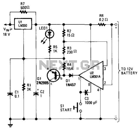
This high-performance charger efficiently charges gelled lead-acid batteries and automatically shuts off upon reaching a full charge. Initially, the charging current is maintained at 2 A; however, as the battery voltage increases, the current gradually decreases. Once the current...
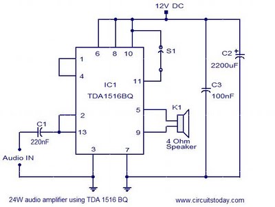
This document presents the circuit diagram of a simple 24W mono amplifier utilizing the TDA1516 integrated circuit. The TDA1516 is a Class B power amplifier housed in a 13-pin SIL package. It incorporates several beneficial features, including short circuit...
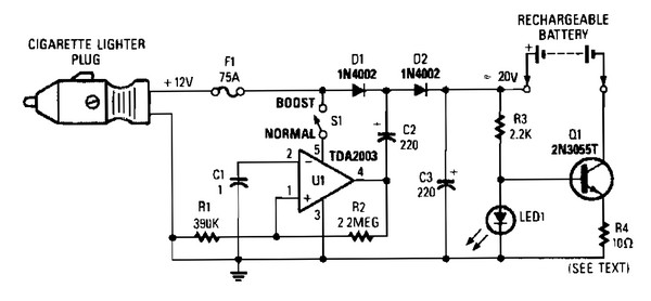
V1 creates a square wave oscillator, while D1 and D2 couple this square wave to a 12-V battery, raising the voltage to over 20 VDC. If this elevated voltage is not required, S1 can remain open. Q1 functions as...
A 6-watt audio amplifier circuit utilizing the TDA2613 is presented here. The TDA2613 is an integrated Hi-Fi audio amplifier IC produced by Philips Semiconductors. The IC is designed for high-quality audio amplification. The circuit features the TDA2613 IC, which is...