
Digital Timer Light Switch

The described circuit functions as a digital timer switch, commonly employed in various lighting applications to automate the on/off states of lights. The core of the circuit typically integrates a microcontroller, such as a PIC (Peripheral Interface Controller) or a custom-designed integrated circuit (IC), which serves as the timing mechanism and control unit.
The circuit is designed to interface with the alternating current (AC) supply, allowing the timer to synchronize its internal clock with the AC line frequency, typically 50 or 60 Hz. This synchronization is crucial as it enables the timer to accurately determine the timing of the trigger pulses. The AC signal is often fed into an optoisolator or zero-crossing detector, which isolates the microcontroller from the high voltage AC line while providing a clean digital signal that represents the AC line's zero-crossing points.
Upon detecting the zero-crossing, the microcontroller can generate precise timing intervals for activating or deactivating the connected load, such as a light bulb. The timing can be programmed or set through user inputs, which may include buttons or a touchscreen interface, depending on the sophistication of the timer module.
Additional components in the circuit may include power supply filtering capacitors, resistors for current limiting, and protection diodes to safeguard against voltage spikes. The output stage typically consists of a relay or a solid-state switch (like a TRIAC) that controls the power delivered to the load, ensuring that the circuit can handle the required voltage and current levels.
Overall, this digital timer circuit showcases a practical application of microcontroller technology in enhancing the functionality and convenience of traditional light switches, allowing for programmable lighting solutions that can improve energy efficiency and user experience.Typical circuit representative of those used in most light switch type digital timers. The timer module is normally a PIC or custom chip, and it syncs to the AC line so that a trigger pulse can be supplied at the right moment. 🔗 External reference
Related Circuits
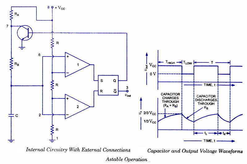
An astable multivibrator, often referred to as a free-running multivibrator, is a rectangular-wave generating circuit. Unlike the monostable multivibrator, this circuit does not require any external trigger to change the state of the output, hence the term free-running. Before...
Touch operated switches are an attractive project for DIY electronics but they are not so common in commercial products. The reason for this is that, although there are many different ways of implementing a touch switch (leakage, hum pickup,...

The following diagram illustrates a 50W offline switching power supply circuit design. This circuit is powered by a MOSFET, specifically the BUZ80A/IXTP4N8 for a 220V AC voltage input and the GE IRF823 for a 110V AC voltage input. The...
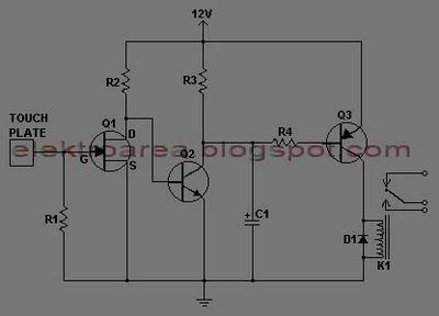
This document describes a series of touch switches that utilize only three transistors. These touch-based transistor switches can activate a load simply by the user touching a metal plate. They are designed to directly switch a relay, enabling operation...
Digital Remote Thermometer. The remote sensor transmits data through the mains supply. The temperature range is from 0.0 to 99.9 °C. Transmitter circuit diagram includes the following components: R1, R3 = 100K 1/4W resistors; R2 = 47Ω 1/4W resistor;...
Normally, home appliances are controlled using switches, sensors, etc. However, physical contact with switches may be dangerous if there is any shorting. The circuit described here requires no physical contact for operating the appliance. It only requires moving a...