
5V/10A 50W Offline Switching Power Supply

The 50W offline switching power supply circuit is a crucial component in various electronic systems, converting high-voltage AC input into a stable low-voltage DC output. The circuit employs a switching topology, which enhances efficiency and reduces heat generation compared to linear power supplies.
The primary components of this power supply include the MOSFETs, which act as the main switching elements. The BUZ80A/IXTP4N8 is utilized for circuits operating at 220V AC, while the GE IRF823 is selected for those operating at 110V AC. These MOSFETs are chosen for their high-speed switching capabilities and low on-resistance, allowing for efficient operation and minimizing power loss.
The circuit typically incorporates a transformer for voltage step-down and isolation, followed by a rectification stage to convert the AC output from the transformer into pulsating DC. This is often achieved using a bridge rectifier configuration. After rectification, the output is smoothed using filtering capacitors to reduce ripple voltage, ensuring a stable 5V DC output.
In addition to these components, a feedback mechanism is usually integrated to regulate the output voltage. This feedback loop monitors the output voltage and adjusts the switching duty cycle of the MOSFETs to maintain a consistent 5V output, even with variations in load or input voltage.
Safety features such as over-voltage protection, over-current protection, and thermal shutdown mechanisms are commonly included in the design to enhance reliability and prevent damage to the circuit and connected devices. Overall, this 50W offline switching power supply circuit design represents a robust solution for providing efficient power conversion in a compact form factor.The following diagram is the 50W offline switching power supply circuit design. The circuit powered by a MOSFET. BUZ80A/IXTP4N8 for 220V AC voltage input and GE IRF823 for 110V AC input voltage. The output will be 5VDC with electric current.. 🔗 External reference
Related Circuits

The circuit is designed to regulate a dual power supply that provides +12V and -12V from the AC mains. Such a power supply is an essential tool for an electronic hobbyist's workbench. The schematic of the circuit includes components...
Charging circuit from the DC power supply switching power supply control The charging circuit described is designed to operate with a DC power supply, utilizing a switching power supply control mechanism. This type of circuit is commonly employed in applications...
In the absence of radiation, no current is drawn. At normal background radiation levels, the power consumption is extremely low. The instrument may be left on for several months without changing batteries. In this way, the detector is always...

The transformer has two primary windings and six secondary windings; the two 120-VAC primary windings and the 6.3-VAC secondary windings are connected in parallel. Modules A and B are identical; therefore, only the components of Module A are specified....
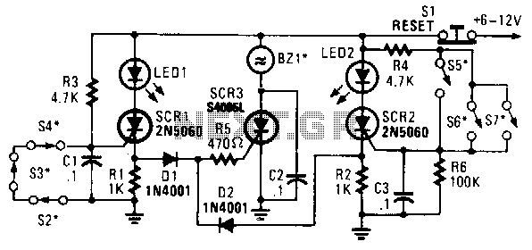
In this circuit, a low-powered silicon-controlled rectifier (SCR) is utilized to trigger a higher-powered SCR. When a switch is opened (S2, S3, S4) or closed (S5, S6, S7), either SCR1 or SCR2 is activated. This action subsequently triggers SCR3...
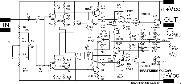
The following circuit illustrates the BUZ902DP 300 Watt Audio Power Amplifier Circuit Diagram. Features include audio frequency linearity from 20 Hz to 20 kHz. The BUZ902DP is a high-performance audio power amplifier designed to deliver up to 300 watts of...