
Digital Vacuum Gauge

The described circuit employs a bridge configuration to effectively convert the readings from a vacuum sensor, represented by IC1, into a usable electrical signal. The bridge circuit is adept at detecting small changes in the vacuum level, which is crucial for applications requiring precise measurements, such as in pressure sensing or environmental monitoring systems.
IC2b plays a critical role by introducing a small offset voltage of approximately 0.2 V. This offset is essential for calibrating the output signal to ensure that the A/D converter, IC4, accurately processes the data without losing sensitivity at lower vacuum levels. The role of IC2b, along with IC2d, as voltage followers is significant; they buffer the signal from the bridge circuit and ensure that the differential amplifier IC2a receives a stable and accurate representation of the input signal.
Differential amplifier IC2a enhances the difference between the two input signals, improving the signal-to-noise ratio and ensuring that the output is more robust against common-mode noise. This amplified output is then directed to IC4, the A/D converter, which converts the analog signal into a digital format suitable for further processing, display, or logging.
Finally, both IC4 and IC1 serve as display drivers, indicating the processed data to the user. The integration of these components within the circuit allows for a coherent and efficient system capable of providing accurate readings from the vacuum sensor, with the capability to display this information in a user-friendly manner. The overall design emphasizes precision and reliability, essential characteristics in electronic measurement systems. A bridge circuit is used to produce a signal from the output of vacuum sensor IC1. IC2b provides about a 0.2 V offset for IC4, the A/D converter. IC2b and d are voltage followers that drive differential amp IC2a. The output of this circuit is used to drive IC4 and IC1, the display drivers.
Related Circuits
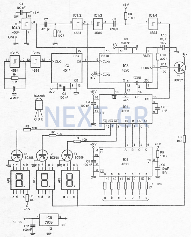
This compact device, designed primarily for modelers, provides instantaneous readings of pulse duration in milliseconds (ms). It can measure servomotor positions, typically ranging from 1 ms to 2 ms, and can also perform repetitive or non-pulsed measurements, such as...
%2Bwith%2Banimation%2Bsimulation%2Bcircuit.png)
The Johnson digital counter, also known as the Twisted Ring Counter, is a synchronous shift register that incorporates feedback from the inverted output (Q`) of the last flip-flop. The Q` output of the final flip-flop is connected back to...
A follow up Mk2 version described by EA's Jim Rowe in the May/June/July 94 issues of EA improved on the original with calibrated time and vertical scales, and extra triggering features. This design proved even more popular than the...
The circuit diagram for a multiple output digital camera power supply using the MAX1802 is illustrated below. The MAX1802 chip features two buck converters and three boost converters. It accepts an input voltage range of 2.5 to 11V and...
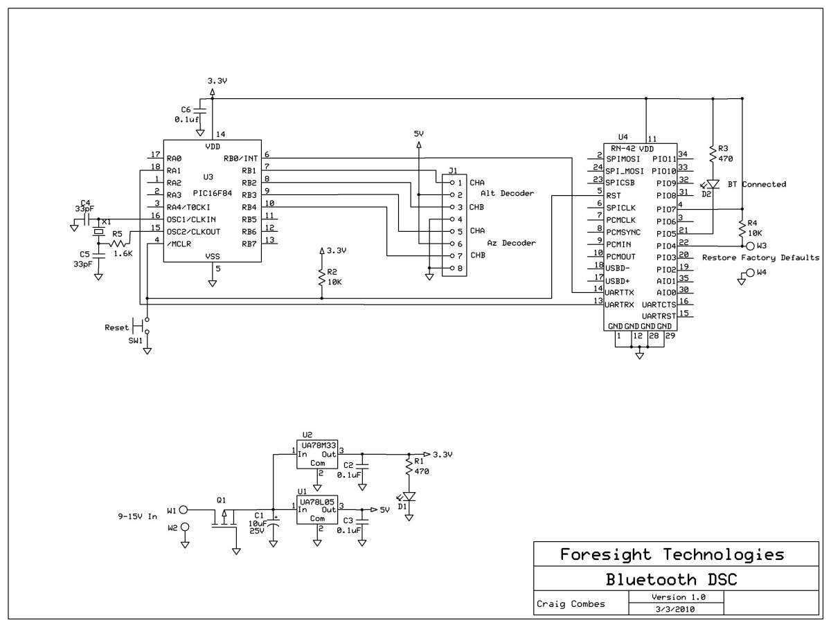
This variation of the Digital Setting Circles project was developed by Craig Combes, who shared his insights for others to replicate his version. Many users utilize Dave's serial DSC board along with a serial to Bluetooth adapter, which can...
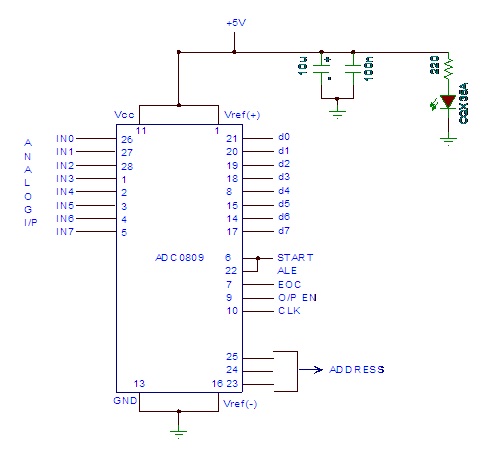
Analog to digital converter modules are utilized in microcontroller-based projects where analog signals need to be transformed into digital signals for further processing in a microcontroller. The integrated chip employed for this purpose is the ADC 0809. This post...