
Digital Volt and Ampere meter

The described circuit is a basic analog-to-digital conversion system designed for measuring either voltage or current, with a focus on displaying the results on a 3-digit seven-segment display. The core components of the circuit include two CA3161E integrated circuits, which serve dual purposes: as analog-to-digital converters (A/D converters) and as BCD to seven-segment decoders/drivers.
The primary function of the CA3161E as an A/D converter is to convert the analog input signal (voltage or current) into a digital representation that can be easily processed and displayed. The circuit is configured to handle two different types of measurements, which are distinguished by their respective input signals. The conversion process involves sampling the input signal and quantizing it into a digital format, which is then sent to the display driving section.
In the display driving section, the CA3161E is utilized as a BCD to seven-segment decoder/driver. This component takes the binary-coded decimal output from the A/D converter and translates it into signals that control the individual segments of the seven-segment display. Each digit of the display is driven by one of the CA3161E ICs (IC2 and IC4), ensuring that the output is correctly formatted for visual representation.
The circuit also incorporates a decimal point feature, allowing users to display measurements with precision. This is particularly important in applications where the distinction between whole numbers and decimal values is critical for accurate readings. The design is straightforward, making it accessible for individuals with basic experience in electronics. It is essential to ensure proper connections and configurations for both the input and output sections to achieve accurate measurements and reliable display functionality.
Overall, this circuit serves as an effective tool for simple voltage and current measurements, providing clear and concise digital readouts suitable for various applications.The circuit does not present particular difficulties for somebody that has a small experience. The two circuits are the himself, with a small difference only in their input, when they have they measure voltage or current and in connection that concern decimal point [ dp ]. In the department of input IC1 and IC3, exist the CA3161E, that is a A/D Converter for 3-Digit Display.
In the drive of Display IC2 and IC4, exist CA3161E, that is a BCD the Seven Segment Decoder/ Driver. 🔗 External reference
Related Circuits
Switching regulator subsystems are designed for use as DC to DC converters. The 3V to 40V DC converter circuit utilizes switching regulators, which are increasingly favored over linear regulators due to the demand for higher conversion efficiency in modern...
The Machtech tester is capable of measuring capacitors; however, it presents challenges when measuring short lead capacitors, particularly surface-mount devices (SMD). Additionally, there is a requirement to measure inductors. Various LC meter schematics were discovered, which are capable of...
Amateur Radio Transmitters using valves such as 807 or 1625 works well with a plate voltage between 600V to 700 Volts. The circuit described here is a full wave voltage doubler. The output voltage is twice the input voltage....
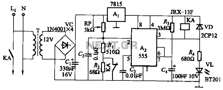
This circuit is applicable in refrigerators and other protective devices. It employs a 7815 three-terminal voltage regulator integrated circuit and an NE555 timer IC configured as a one-shot circuit for delay control. When the voltage drops below 180V, relay...
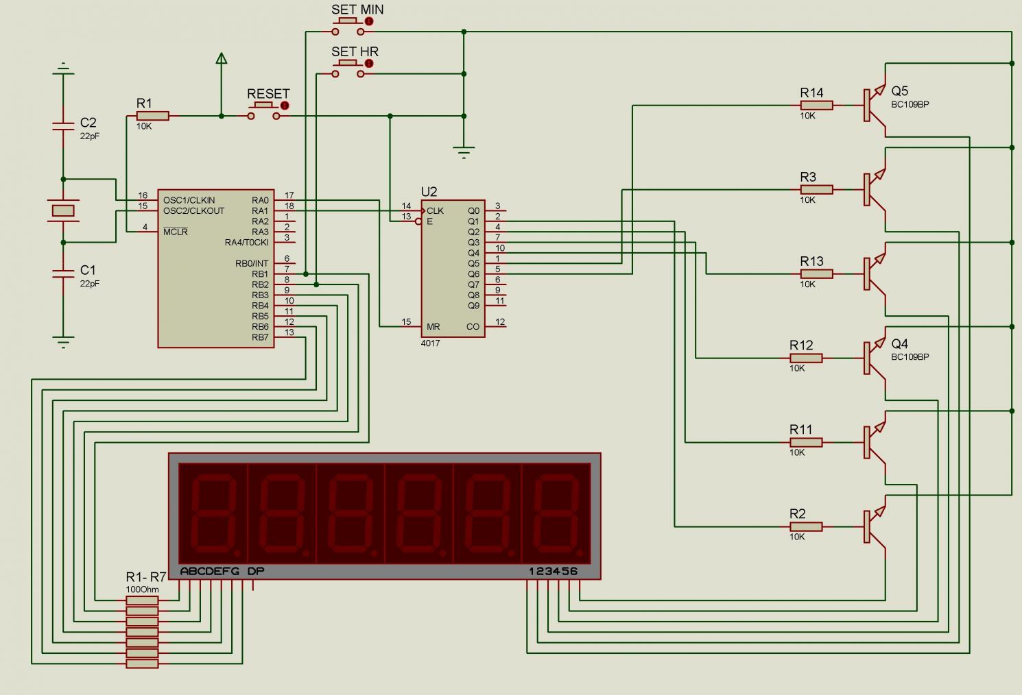
There are issues with simulating this circuit on Proteus. Please review it to ensure no errors were made. The user is also a novice. The circuit simulation in Proteus can often present challenges, especially for those who are new to...
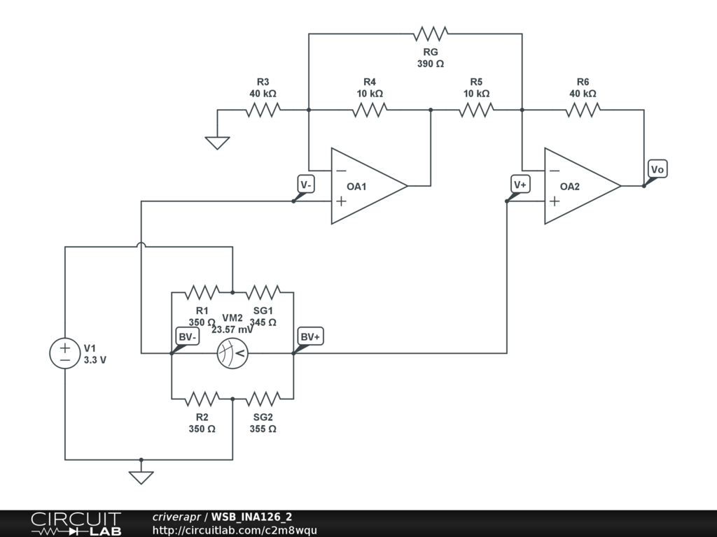
A half-bridge setup is utilized with strain gauges and an INA126 to amplify the voltage. The voltage can be read accurately when the lever is bent in one direction; however, no reading is obtained when the lever is bent...