
infrared detector circuit

The infrared detector circuit operates on the principle of light detection using a photo transistor, which is sensitive to infrared radiation. The RS-276-145 photo transistor is the critical component that responds to infrared light by changing its conductivity. When infrared light strikes the surface of the photo transistor, it generates a small current, which is then amplified by the transistor.
The circuit configuration is simple: the photo transistor is connected in series with a 330-ohm resistor and the LED. The LED is connected in parallel to the photo transistor. When the photo transistor detects infrared light, it allows current to flow through the circuit, causing the LED to illuminate. The 330-ohm resistor serves to limit the current flowing through the LED, preventing it from burning out due to excessive current.
This type of circuit can be used in various applications, including remote control systems, motion detection, and safety alarms. The simplicity of the circuit design allows for easy integration into larger systems or standalone applications. Additionally, the use of a general-purpose LED makes it cost-effective and readily available for various projects.
For optimal performance, the circuit can be adjusted by changing the resistor value or using different photo transistors, depending on the specific requirements of the application. Proper placement of the components is also essential to ensure that the photo transistor has a clear line of sight to the infrared light source, maximizing detection efficiency.Here is a very simple infrared detector circuit which can be used to detect infrared light. The circuit is consist of only three components a RS-276-145 photo transistor, 330 Ohms resistor and a general purpose LED (Light Emitting Diode). When the photo transistor will receive any IR on its surface it will 🔗 External reference
Related Circuits
%2BCircuit%2Bdiagram%2Busing%2BCD4047%2Band%2BIRFZ44%2Bpower%2BMOSFET.png)
This simple low-power DC to AC inverter circuit converts 12V DC to either 230V or 110V AC. By making simple modifications, it is also possible to convert 6V DC to 230V AC or 110V AC. This inverter can be...

It is often desirable for a single doorbell to be operated by two buttons, for instance, one at the front door and the other at the back door. The additional button, S2 in series with the break contact of...

This circuit was originally designed to detect weak flashes of laser light reflected off a fabric video projection screen. It was utilized as part of a firearm training system. The circuit generates a 100 ms output pulse whenever it...

The figure illustrates the actual application circuit for the TDA8351/8356. In this circuit, a 50V voltage feedback (VFB) is connected in series with a 33-ohm resistor. Signals are input at pins 1 and 2, where pin 1 receives a...
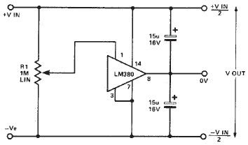
A simple split power supply circuit can be designed using the schematic diagram based on the LM380 audio power integrated circuit (IC). The output voltage regulation is dependent on the circuit feeding the LM380. The power dissipation is approximately...

This light sensor switch circuit enables the automatic activation of a lamp when ambient light levels are low (such as during nightfall) and keeps the lamp illuminated for a specified duration. When transistors T4 and T5 are activated, the...