
Digitaxly tuned low power active filter

This circuit functions as a versatile filter, capable of producing three distinct output types: low-pass, bandpass, and high-pass. The constant gain characteristic ensures that the output amplitude remains stable across the frequency spectrum, while the constant Q factor allows for a narrow bandwidth around the center frequency, enhancing selectivity.
The filter's design is centered around the use of operational amplifiers (op-amps) configured in feedback loops, which help achieve the desired gain and Q factor. The choice of component values is critical; resistors and capacitors are carefully selected to set the center frequencies at 235 Hz and 23 Hz for high and low logic inputs, respectively. The Q factor of 100 indicates a high degree of resonance at the center frequency, making the filter particularly effective for applications requiring precise frequency selection.
In practical applications, this type of filter can be employed in audio processing, telecommunications, and signal conditioning, where simultaneous access to different frequency bands is required. The low-pass output allows for the passage of signals below a certain frequency, the bandpass output isolates a specific frequency band, and the high-pass output enables the transmission of signals above a designated frequency.
The implementation of this filter requires careful consideration of power supply requirements, as well as layout and grounding techniques to minimize noise and distortion. Properly designed, this filter can significantly enhance signal integrity in various electronic systems.Constant gain, constant Q, variable frequency filter which provides simultaneous low-pass, bandpass, and high-pass outputs With the component values shown, center frequency will be 235 Hz and 23 Hz for high and low logic inputs respectively, Q = 100, and gain = 100.
Related Circuits
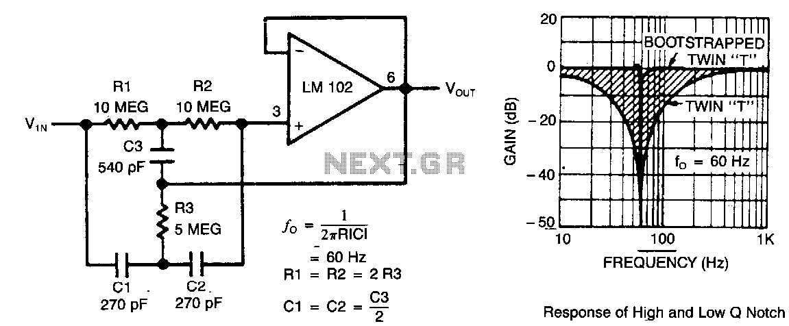
This circuit illustrates a twin-T network connected to an LM102 to form a high-Q, 60-Hz notch filter. The junction of R3 and C3, which is typically grounded, is bootstrapped to the output of the follower. Due to the low...
The circuit was designed to generate an oscillator that operates at low frequencies, intended for use in electronic music production, experimentation, and testing. The low-frequency oscillator (LFO) circuit typically consists of several key components, including resistors, capacitors, and an operational...
The FM Wireless Microphone has gained popularity among both beginners and experienced constructors. It has been utilized in guitars and as a component of remote control systems. There have been numerous requests for a higher-powered circuit with improved microphone...
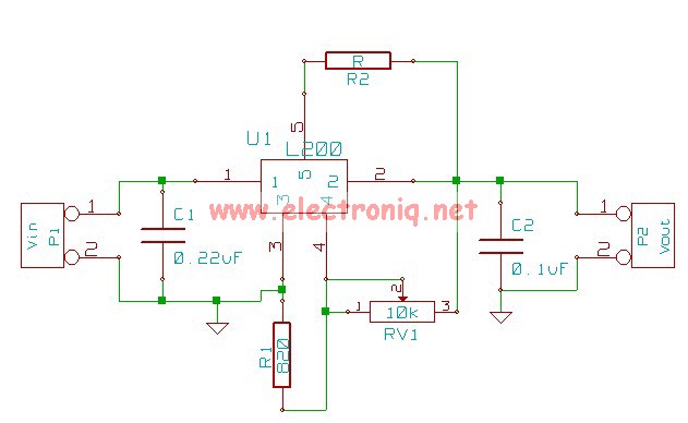
The following circuit illustrates the L200 Regulator Power Supply Circuit Diagram. Features include its use in power supply applications with specified voltage and current. The L200 voltage regulator is a versatile and adjustable linear regulator designed for various power supply...
Figure 1 shows the circuit. A major change from all of the designs from that era is the speaker coupling capacitor - 1000uF (for a -3dB of 20Hz and a 8 Ohm load) was the most common value. This is...
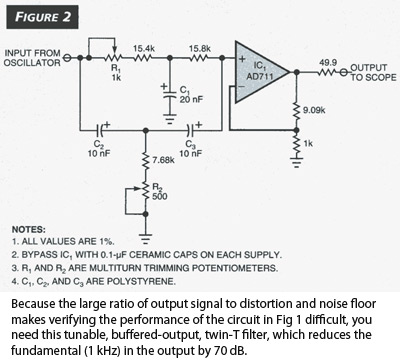
The Wien-bridge sine-wave oscillator utilizes a light bulb for amplitude stabilization. The circuit depicted in Fig 1 omits the light bulb and incorporates several enhancements that reduce distortion and produce a test signal sufficiently pure for evaluating modern operational...