
Dimmable Fluorescent Lights Bulbs

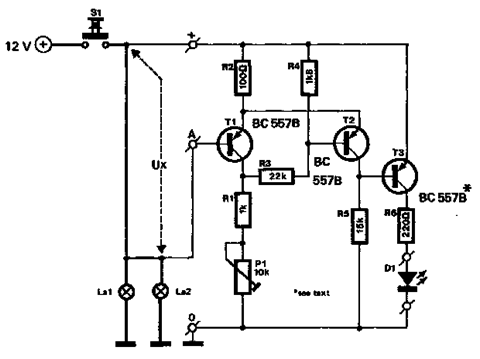
The described dimmable fluorescent light circuit incorporates several key components to achieve both the starting and brightness adjustment of fluorescent tubes. At its core, the circuit includes a choke coil, which is essential for creating the necessary high voltage to ignite the fluorescent tube. The choke coil works by inducing a back EMF (electromotive force) when current is interrupted, thus generating the required voltage spike.
In addition to the choke, the circuit features a starter component that can be a thermal or electronic starter. This component is responsible for momentarily allowing a high current to flow through the filaments of the fluorescent tube, thereby heating them up to facilitate the ionization of the gas within the tube. After the tube ignites, the starter disconnects, allowing the tube to operate at the lower supply voltage.
The brightness control potentiometer, P1, is a variable resistor integrated into the circuit, allowing users to adjust the amount of current flowing through the fluorescent tube. By altering the resistance, the potentiometer can effectively control the brightness of the light emitted. When initially powering the circuit, it is crucial to set the potentiometer to its maximum position to ensure the tube receives enough current to start properly.
Overall, the design of this dimmable fluorescent light circuit not only improves the usability of fluorescent lighting by allowing for brightness adjustments but also simplifies the starting process by integrating the functions of traditional starters within the circuit. This results in an efficient and user-friendly solution for controlling fluorescent lighting in various applications.The brightness of a fluorescent light bulb or neon tube cannot adjust as easily as that of a incandescent bulb because it starts only when a voltage is much higher than that of the network, then remains on at electrical network voltage. Normally, the high starting voltage is obtained by the interruption of current that circulates through a choke c
oil. This is usually a starter to ensure a sufficiently large current through the tube filaments. These starter functions are taken over by this dimmable fluorescent light circuit presented which also allows adjustment of the fluorescent bulbs brightness. When we switch on the neon tube, the brightness control potentiometer, P1, should be placed on the position of maximum brightness, in order to facilitate the start.
🔗 External reference
Related Circuits
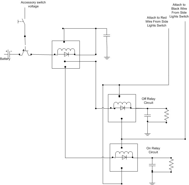
A decision has been made to install daytime driving lights for an Elise vehicle. The intention is to eliminate the need for manually pressing the button on and off repeatedly. The installation of daytime driving lights (DRLs) enhances vehicle visibility...
This sound-controlled lighting circuit design is utilized to adjust the brightness of connected lights in synchronization with captured sound. The sound-controlled lighting circuit operates by detecting audio signals through a microphone or sound sensor. The circuit typically consists of several...
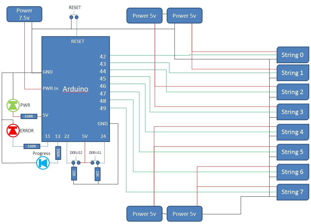
This project develops a Christmas lights controller for GE Color Effects lights, enabling programmed control of up to eight sets of lights. It includes a function-specific language for programming light patterns and an emulation environment for testing programs before...
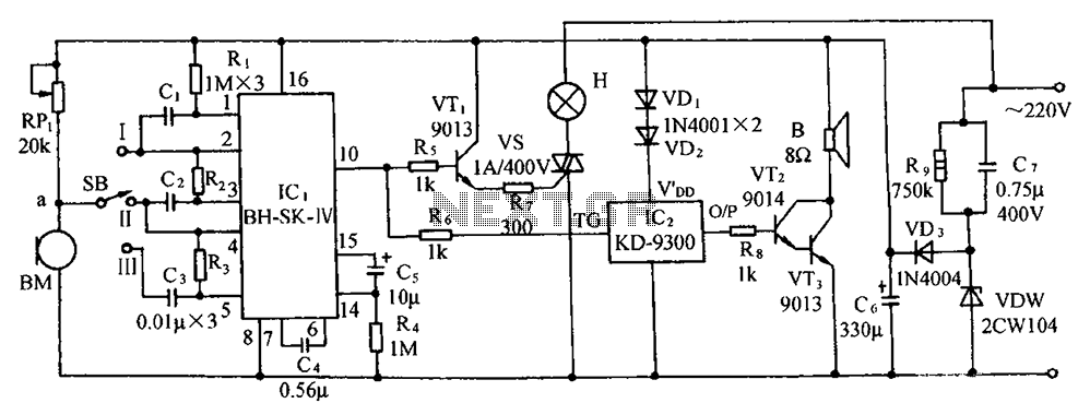
The circuit includes a microphone transducer, voice circuits, an SCR control circuit, a vocal music buck rectifier circuit, and an AC circuit. The BH-SK-IV serves as the core of the device. The described circuit is a complex assembly designed to...
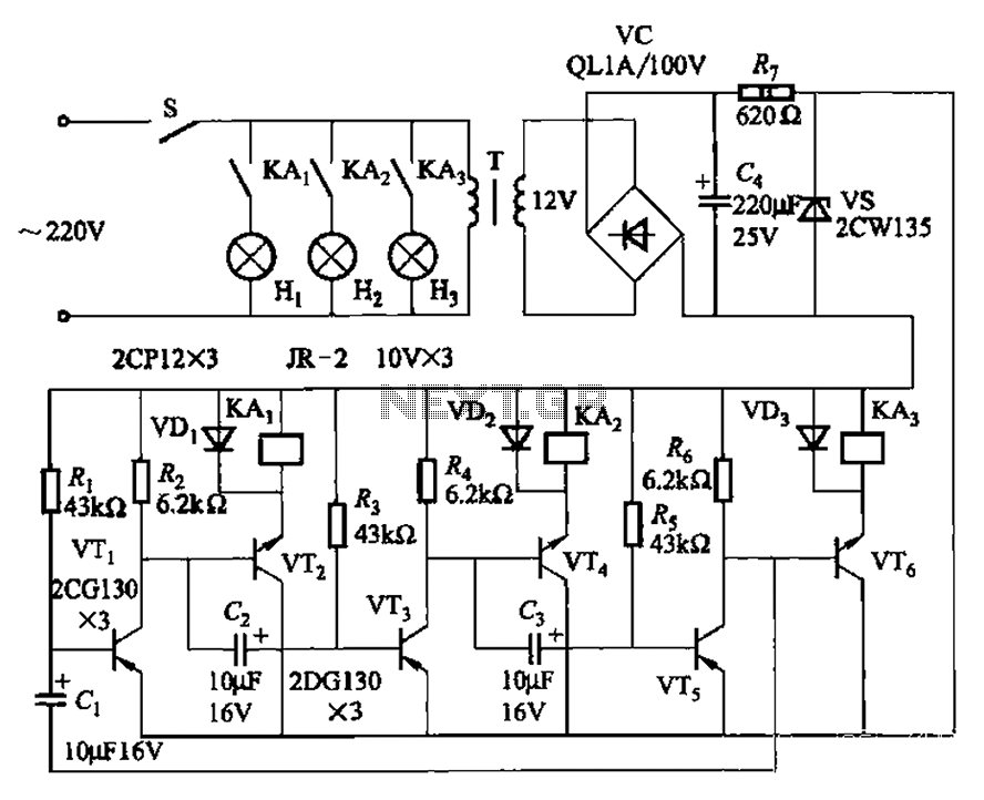
The transistors VTi, VT3, and VTs, along with the RC components, form three distinct multi-resonator oscillators. The oscillation frequency levels are dependent on the values of Ri, R3, Rs, and Cl, as well as Cz and C3s. The circuit comprises...
The circuit described below monitors the car's brake lights and indicates their operational status using a 12V light-emitting diode (LED). This functionality can prevent fines for driving with defective brake lights and enhance road safety. The monitor relies on...