
Dimmer circuit

More: The circuit typically employs a triac such as the BTB04-600SL (manufactured by ST Semiconductors, rated for 600V and 4A with a trigger current of 10mA) and a diac or trigger diode like the DB3, which activates at approximately 32V. Inductors used in these circuits generally have a value around 3mH, although variations exist, with some designs utilizing a 50uH inductor, T0609MJ, and BR100. It is essential to ensure that the maximum ratings of all components are not exceeded. Additionally, it is possible to find triacs and diacs integrated into a single package; an example includes a silicon device discovered in a vacuum cleaner. For a motor with a power rating of about 1500W, the triac-diac combination should be paired with a small aluminum heat sink (approximately 8 square centimeters in size).
The described dimmer circuit operates by controlling the phase angle of the AC voltage supplied to the load, effectively reducing the power delivered to incandescent lamps and allowing for variable speed control in motors. The triac acts as a switch that turns on and off at specific points in the AC cycle, while the diac provides a triggering mechanism to initiate the conduction of the triac.
When the AC voltage rises to the breakdown voltage of the diac, it conducts and triggers the triac, allowing current to flow through the load until the AC cycle crosses zero, at which point the triac turns off. The inductor plays a critical role in smoothing the current and preventing high-frequency noise, contributing to the stability of the circuit.
In designing this dimmer circuit, careful attention must be paid to the component ratings, ensuring that the triac can handle the maximum load current and voltage without overheating or failing. Adequate heat dissipation measures, such as the use of heat sinks, are essential to maintain the reliability and longevity of the components.
Overall, while the circuit may appear simple, the underlying principles of phase control and component selection are crucial for achieving the desired performance and efficiency in dimming applications.Dimmer, from the word n. dim, v. to dim . Simple device to make light of incandescence lamps lower. Also, used to slow down colector motors. All this started because Lithuanian internet is full of old soviet circuits with archaic components. Meanwhile other world is using much better way to dim lamps. Component selection is not very critical: triak BTB04-600SL (ST semiconductors, 600V, 4A, trigger curent 10mA), diak or trigger diode- DB3 ( fire at 32V), inductors was about 3mH. There are lots of versions of this circuit in the internet. In one version I saw 50uH inductor, T0609MJ and BR100. Just check if maximum allowed values are not outmeasured. Also, it is posible to find triak and diak in one package. I found one packade silicon device in some vacuum cleaner. As power of motor was about 1500W, triak-diak was with small aluminium cooler (~8 square centimeters).
🔗 External reference
Related Circuits
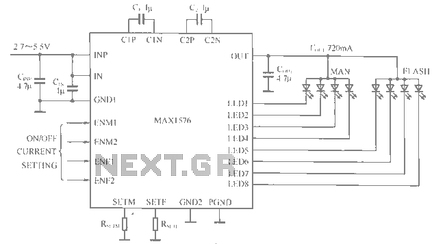
The MAX1516 charge pump drives up to 8 white LEDs with constant current regulation to achieve uniform light intensity, capable of delivering up to 30mA per LED for backlighting. The flash group LEDs (LED5 to LED8) are individually controlled,...
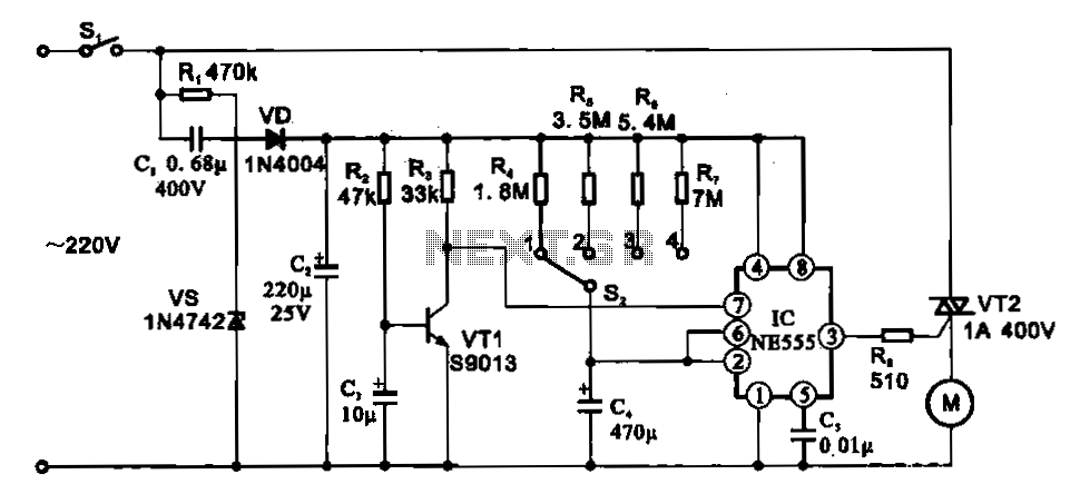
The fan motor driving circuit is depicted as a basic configuration comprising a power circuit and a motor drive circuit. The power supply circuit primarily consists of a power switch (SI), a capacitor (C1), resistors (R1), a Zener diode...
A JFET-bipolar cascode circuit is designed to deliver complete video output for driving the cathode of a CRT. The configuration offers an approximate gain of 90. The cascode arrangement mitigates issues related to the Miller capacitance of the JFET...
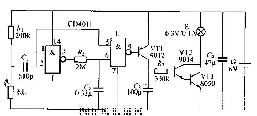
A battery-powered light control circuit is designed to delay the lighting of a small lamp during sudden power outages or nighttime situations when a blown fuse leaves a room in darkness. This circuit addresses the difficulty of locating matches...
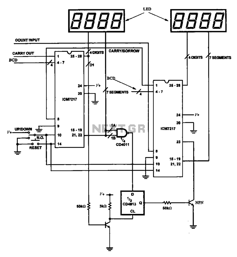
Figure 8 illustrates a potential digital counter circuit. This circuit employs two ICM7217 integrated circuits, with each controlling four digital display tubes. The digital counter circuit primarily utilizes the ICM7217, a highly integrated chip designed for driving seven-segment displays. Each...
This circuit utilizes a single 555 Timer IC and a small transformer to generate high voltage for testing zener diodes with voltage ratings up to 50VDC. The 555 timer operates in astable mode, with the output at pin 3...