
dimmer Controller circuit

The circuit operates on a 12-volt power supply, which is connected to a lamp rated at 20 watts. This setup requires careful attention to battery polarity to ensure proper operation. The control mechanism is facilitated by a momentary push-button switch, which serves multiple functions based on the duration of the press. A brief press activates the lamp, while repeated presses enable cycling through various brightness levels, allowing users to adjust the intensity according to their preference. The functionality is further enhanced by a long press, which turns off the lamp entirely.
The design includes a microcontroller programmed with assembly code, which governs the logic for the button interactions and manages the lamp's power levels. The provided assembly code is commented for clarity, enabling users to understand and modify it as necessary. The hex code allows for easy uploading to the microcontroller, facilitating quick updates to the firmware.
Additionally, the circuit is designed with expandability in mind. It includes 11 available I/O lines, permitting the integration of more components such as additional HEXFETs for controlling multiple lamps or other devices, as well as extra buttons for more complex user interfaces. The EEPROM memory feature is particularly useful, as it can store user preferences or last-used settings, ensuring that the lamp resumes its previous state after a power interruption.
In summary, this circuit design offers a versatile and user-friendly approach to controlling a 12-volt lamp with the potential for further enhancements and customizations, making it suitable for various applications.Connect a 12 volt 20 watt lamp and 12 volt battery to the circuit (observe battery polarity). Momentarily press and release the button to turn the lamp on. Repeatedly press the button to cycle through the power levels. Pressing and holding the button will turn the lamp off. I have provided commented assembly code as well as the hex code for progra mming. Feel free to modify or add to the code as you wish. The basic circuit can easily be expanded to control additional HEXFETs, additional buttons, etc. There are 11 more I/O lines open for use. Also, the EEPROM memory could be used to "remember" settings when power is turned off. 🔗 External reference
Related Circuits
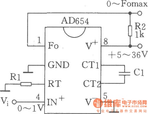
The circuit depicted is a low-cost voltage frequency converter (VFC) utilizing the AD654 component. By connecting the required components, Rl and Cl, as shown in the figure, a functional VFC application circuit can be established. The supply voltage can...
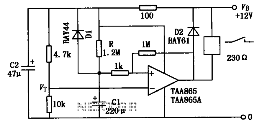
The circuit illustrated in the figure is a delayed release operational amplifier relay circuit. When the power switch is activated, a resistor of 4.7k is connected to the inverting input terminal of the operational amplifier. Additionally, a 10k resistor...
This infrared light valve has more parts, so it works better and more reliable for alarms. The circuit responds less ambient light. The light valve consists of a transmitter and a receiver. The transmitter consists of a NE 555...
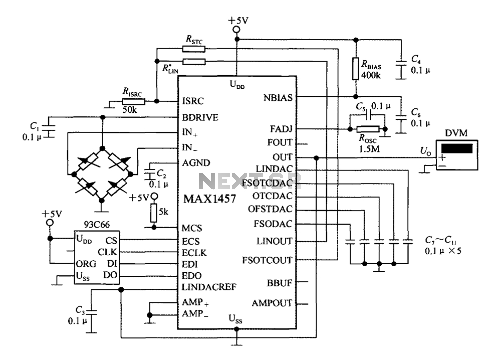
The circuit diagram illustrates a digital precision pressure tester using the MAX1457 integrated circuit with an external ROM selection of the 93C66 type, which is a 4096-bit E2PROM. Upon powering on, the MCS pin is pulled to a high...
With this circuit we can change the brightness of lamb, with a only key of touch. The key of touch is connected in the circuit, center of which is a special completed IC1, which is the S566B of SIEMENS....
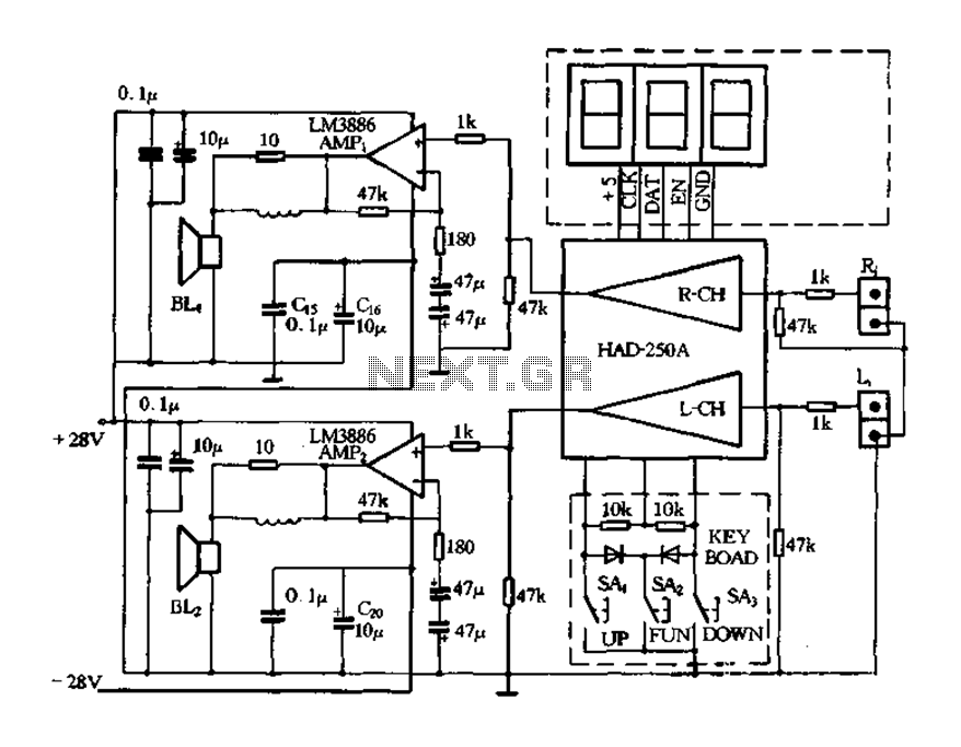
Figure 4-20 illustrates the HAD250A-3 active speakers and amplifier circuit, which features the LM3886 integrated amplifier. This circuit operates with a 25V power supply and delivers an output power of up to 50W per channel, making it suitable for...